Dynamic heat sink engine

a technology of heat sink engine and heat sink, which is applied in the field of closed-circuit engines, can solve problems such as sudden collapse of the tank pressur

Inactive Publication Date: 2006-06-15
ROBERTSON STUART J +1
View PDF18 Cites 0 Cited by
  • Summary
  • Abstract
  • Description
  • Claims
  • Application Information

AI Technical Summary

Benefits of technology

[0009] The disclosed heat sink engine is capable of electrical power production if atmospheric heat or another fluid is utilized as a heat source in conjunction with a cryogenic working fluid. In the case of using atmospheric heat, the preferred working fluid would be liquid hydrogen, although other fluids may be used for particular applications. In addition, the disclosed heat sink engine may also be used to store energy in the form of liquified gas during off-peak hours. Later, during peak hours, the stored energy may be utilized by pumping the liquid gas, vaporizing the liquid gas, and then driving an expansion turbo-generator. In this application, the apparatus of the present invention would enhance the efficiency and effectiveness of a conventional power plant by providing a bottoming cycle.
[0014] Optionally, a second heat exchanger may be provided in thermal communication with the working fluid circuit. Preferably, the second heat exchanger is located at the output stream from the first heat exchanger and is in thermal communication therewith. The second heat exchanger also has an input and output fluid circuit in thermal communication with the liquefier. This second heat exchanger thereby acts as a heat sink for the liquefier, lowering the heating duties of the heater and also increasing the coefficient of performance of the liquefier.

Problems solved by technology

For example, it has been determined that pumping liquid oxygen from a storage tank and then returning the liquid oxygen into the same tank will suddenly collapse the tank pressure.

Method used


Image

  • Dynamic heat sink engine
  • Dynamic heat sink engine
  • Dynamic heat sink engine

Examples


Embodiment Construction

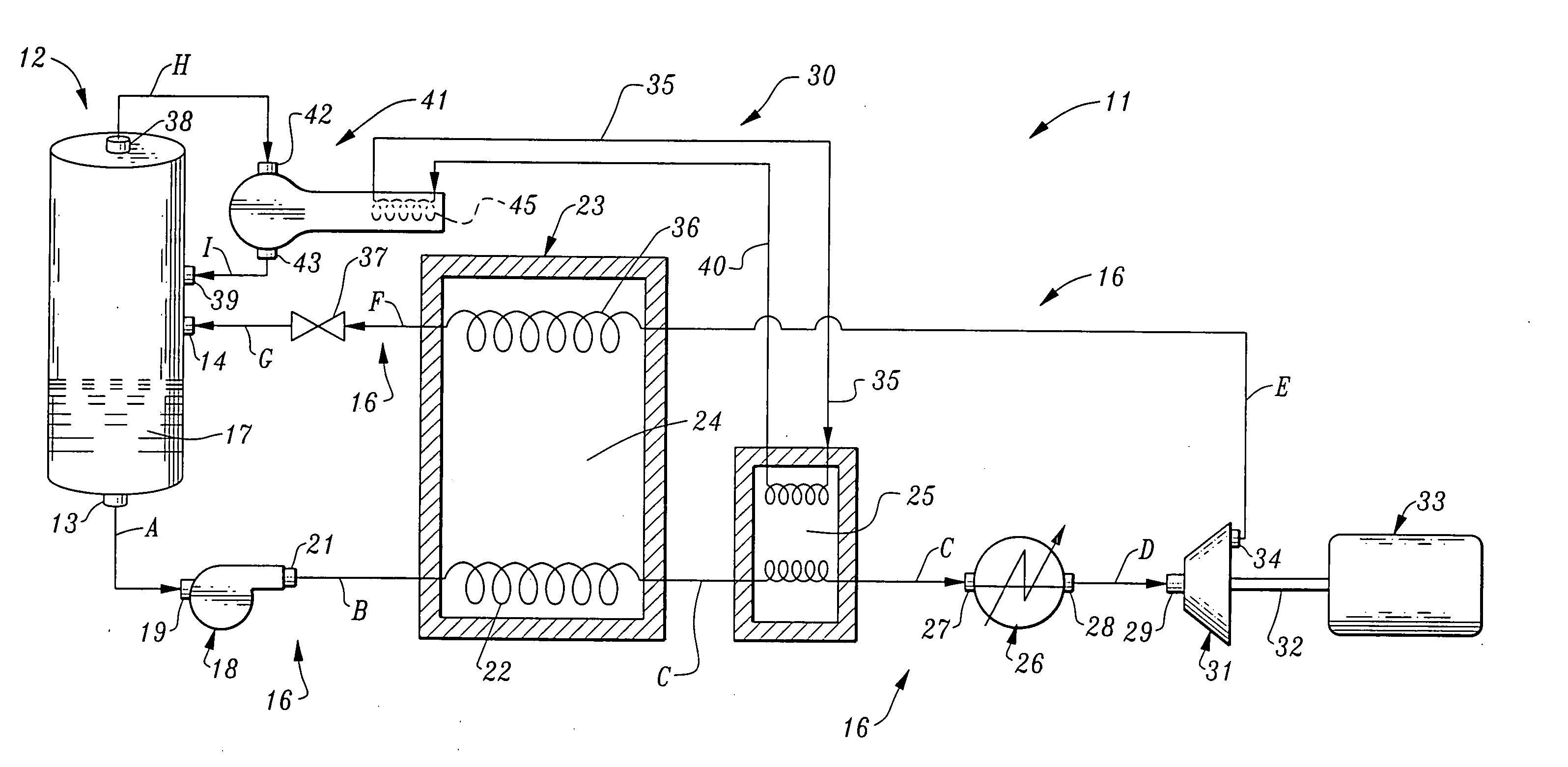
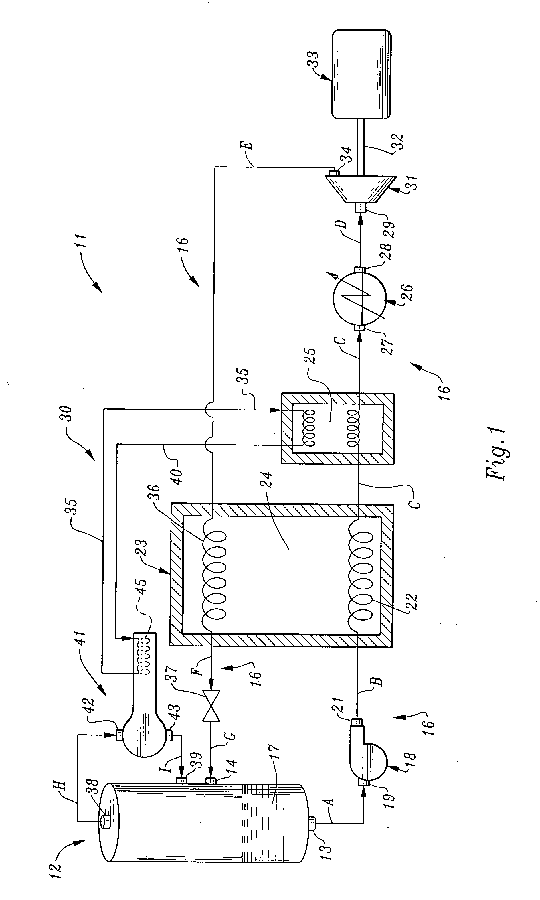
[0019] Turning now to the drawings, and in particular to FIG. 1, the invention comprises a dynamic heat sink engine 11, including a storage vessel 12 having a working fluid outlet 13 and a working fluid inlet 14. A closed-loop, first working fluid circuit 16 extends between the working fluid outlet 13 and the working fluid inlet 14. A lower portion of storage vessel 12 contains an amount of cryogenic working fluid 17 in liquid form, which is maintained at or near its boiling point. Working fluid 17 is preferably hydrogen, as it is readily available and it is a renewable resource. Other fluids may also be used as the working fluid, such as liquid natural gas or helium.

[0020] The working fluid 17 in vessel 12 is preferably maintained approximately 3 to 5 psi above ambient pressure, to prevent contamination from atmospheric gas, such as wet air. Fluid 17 is also maintained below critical temperature and pressure, for apparent safety reasons. If it can be established as safe in an indu...


PUM


Abstract

A dynamic heat sink engine including a storage vessel having a working fluid outlet and a working fluid inlet. The lower portion of the storage vessel contains a cryogenic working fluid, such as liquid hydrogen, at a temperature at near its boiling point. The engine further includes a working fluid circuit extending between the working fluid outlet and the working fluid inlet of the storage vessel. The working fluid circuit includes the serial connection of the following components from the working fluid outlet to the working fluid inlet: a fluid pump; a vaporizer having a liquid line passing therethrough; a heater; an expansion engine having a rotary output shaft; an electrical generator connected to the rotary output shaft of the expansion engine; a vapor line passing through the vaporizer, the vaporizer including a heat exchanger providing thermal communication between the liquid line and the vapor line.

Description

CROSS-REFERENCE TO A RELATED APPLICATION [0001] None BACKGROUND OF THE INVENTION [0002] 1. Field of the Invention [0003] The invention relates generally to apparatus for both generating and storing energy through the use of cryogenic fluid as a working fluid. More particularly, the invention pertains to a closed loop heat sink engine, which produces power utilizing low boiling point fluids heated by atmospheric heat or other available heat such as waste heat from a conventional electrical power plant. Additionally, the invention pertains to a heat sink engine capable of storing surplus energy in the form of liquified gas during off-peak production periods, in which the liquified gas is later utilized to produce electrical power during peak or high demand periods. [0004] 2. Description of the Prior Art [0005] Electrical power generation plants utilize a number of different energy sources including nuclear, hydroelectric, solar, wind, and fossil fuels. In most regions of the world, fo...

Claims


Application Information

Patent Timeline
Patent Type & Authority Applications(United States)
IPC IPC(8): F01K23/06
CPCF01K25/08F01K25/10F03G6/003F03G7/04Y02E10/46F03G6/004
Inventor ROBERTSON, STUART J.TELLIER, NILS E.
Owner ROBERTSON STUART J
Why Eureka
Try Eureka