
Method and apparatus for seismic feature extraction

a technology of seismic feature extraction and method, applied in the field of seismic feature extraction, can solve the problems of inability to isolate fine details, limited precision of existing technologies, etc., and achieve the effect of being convenient to us

Inactive Publication Date: 2006-06-08
GEOENERGY
View PDF6 Cites 86 Cited by
  • Summary
  • Abstract
  • Description
  • Claims
  • Application Information

AI Technical Summary

Benefits of technology

[0011] A preferred embodiment of the present invention provides a method and apparatus for extracting, separating, and labeling geologic features (such as fault surfaces) in seismic data, which is of significant benefit in the art of hydrocarbon exploration. The method includes steps of: a) reading a three dimensional seismic data volume; b) computing the three-dimensional orientation of the subsurface; c) subdividing the original volume into small data volumes that are rotated at a predetermined set of dips and azimuths related to those of the subsurface orientation; d) computing a 3-D edge detection measure on the small volumes formed in step c; e) performing a 3-D contrast enhancement operation in each of the small volumes; f) filtering the result of the contrast enhancement with selected 3-D filters at the predetermined set of dips and azimuths; g) skeletonizing the results of the filtering operation; h) separating the individual fault surfaces, and i) labelling the individual fault surfaces for further interpretation and exploration. The ultimate result obtained by a preferred embodiment of the present invention provides a visual and semantic representation of a set of well-defined, cleanly separated, one-pixel-thick labelled fault surfaces, which is readily usable for seismic interpretation.

Problems solved by technology

These existing technologies, however, have a limited precision, and are incapable of isolating fine details, such as fault surfaces or sedimentary layer interfaces that may be only one pixel wide.

Method used


Image

  • Method and apparatus for seismic feature extraction
  • Method and apparatus for seismic feature extraction
  • Method and apparatus for seismic feature extraction

Examples


Embodiment Construction

)

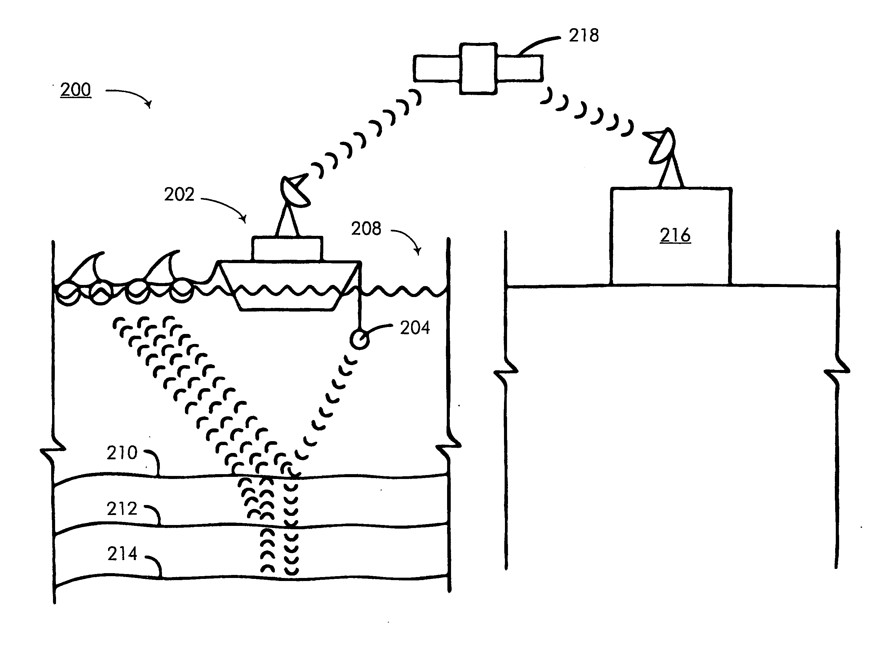
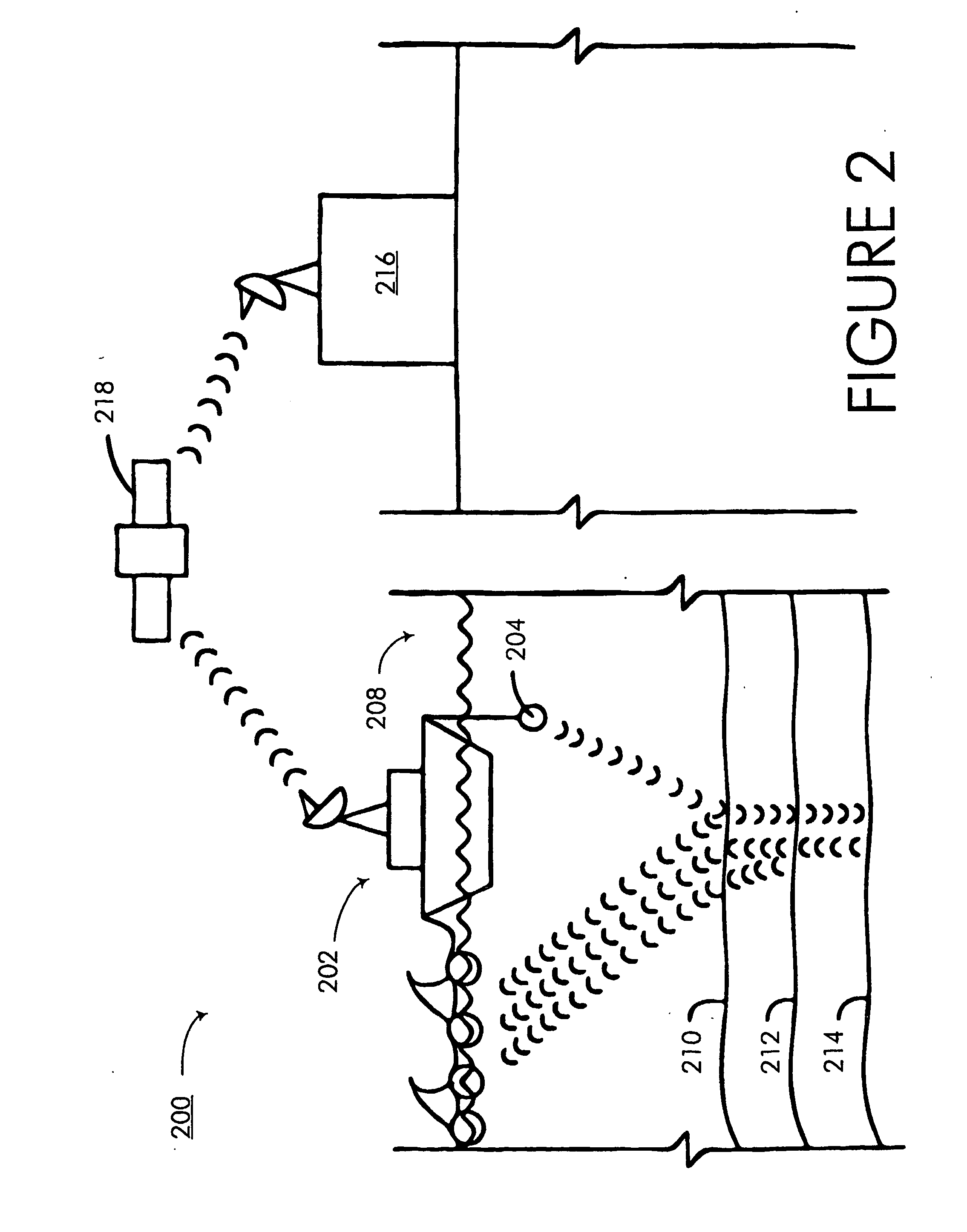
[0021] Referring now to the drawings, FIG. 1 provides a schematic representation of an oceanic seismic survey system 100 of the type used to obtain seismic data which can be processed in accordance with preferred embodiments of the present invention. The system 100 includes the use of a seismic vessel 102 having an acoustic wave source 104 and a towed array of spaced-apart receivers 106. For example, the towed array can comprise a total of four to eight streamer cables which are towed in parallel behind the vessel 102, with each cable having a large number (such as 240) of the floatable receivers 106 which are serially attached to the cable.

[0022] During operation, the vessel 102 transverses the surface of an ocean 108 in a regular pattern while periodically directing acoustic wave energy (referred to as “shots”) downwardly from the source 104. The wave energy is reflected back to the receivers 106 at an ocean floor boundary 110, as well as at subterranean boundaries (such as 112,...


PUM


Abstract

A method and apparatus for seismic image processing is disclosed. A preferred embodiment aids in the identification of subterranean faults, which are significant in hydrocarbon exploration. The method includes steps of: a) reading a three dimensional seismic data volume; b) computing the three-dimensional orientation of the subsurface; c) subdividing the original volume into small data volumes that are rotated at a predetermined set of dips and azimuths related to those of the subsurface orientation; volumes formed in step c; e) performing a 3-D contrast enhancement operation in each of the small volumes; f) filtering the result of the contrast enhancement with selected 3-D filters at the predetermined set of dips and azimuths; g) skeletonizing the results of the filtering operation; h) separating the individual fault surfaces, and i) labelling the individual fault surfaces for further interpretation and exploration.

Description

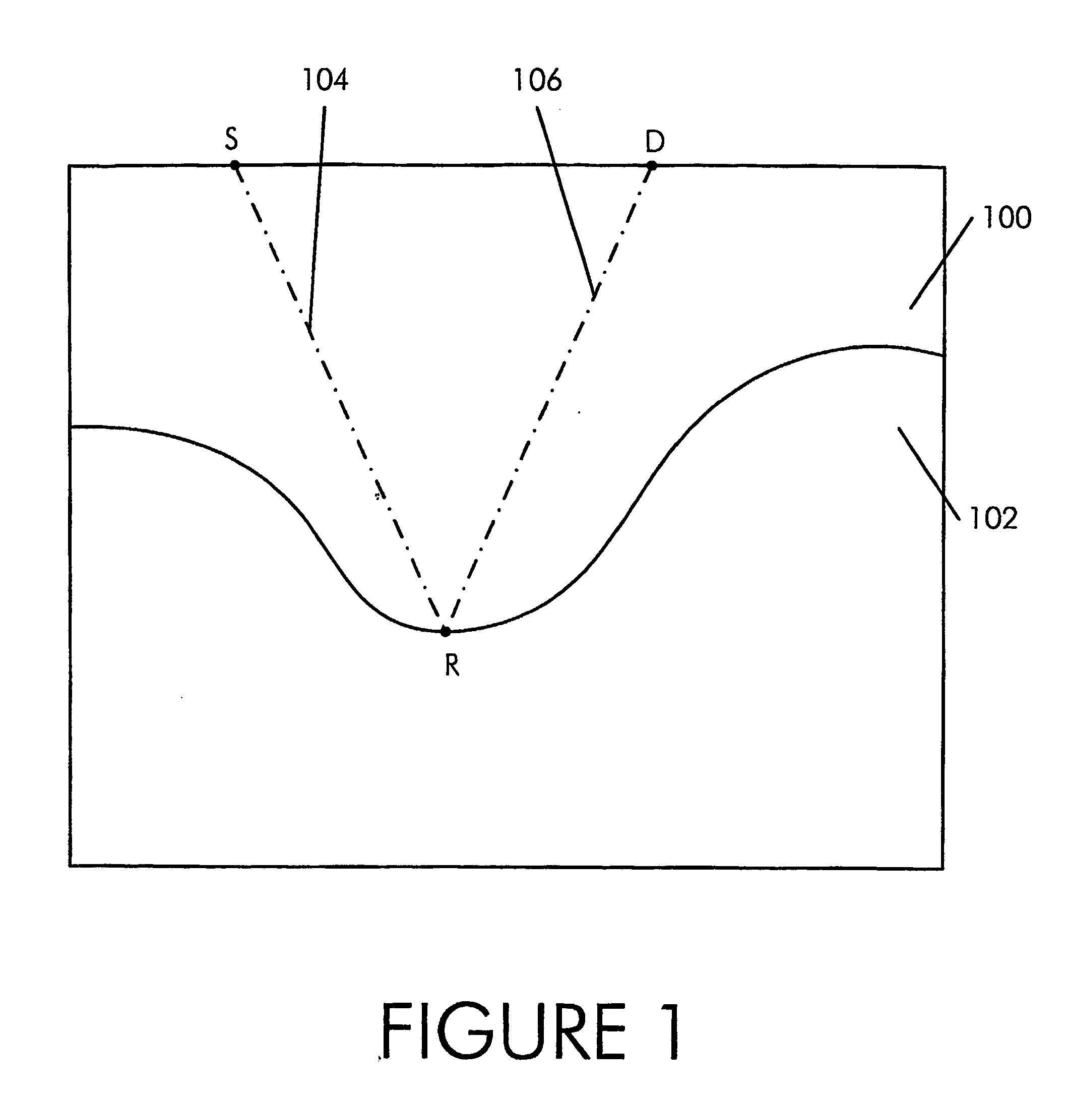
TECHNICAL FIELD [0001] The present invention relates generally to improvements in the field of seismography. In particular, the present invention provides a method and apparatus for processing seismic image data to more clearly reveal geologic features such as faults. BACKGROUND ART [0002] Almost all geophysical exploration, and in particular hydrocardon exploration, includes the use of seismic methods. Seismic exploration generally begins with a seismic data acquisition in an area that has been identified as promising for hydrocarbon exploration. Seismic data acquisition surveys use acoustic sources (generally referred to as “shots”) as a source of seimic waves. Those seismic waves propagate radially through the ground in accordance with the acoustic impedance (analogous to electrical impedance in electric circuit theory) of the geologic layer(s) through which the waves travel. For example, in, point S represents the location of such an acoustic source with respect to a vertical cr...

Claims


Application Information

Patent Timeline
IPC IPC(8): G01V1/00G01V1/28G01V1/30G01V1/36
CPCG01V1/288G01V1/30G01V1/301G01V1/364
Inventor COHEN, ISRAELVASSILIOU, ANTHONYCOULT, NICHOLAS
Owner GEOENERGY
Learn More