Apparatus and method for guiding a tool along a path on a surface

Inactive Publication Date: 2006-06-08
MOBILGLAS 2000
View PDF12 Cites 31 Cited by
  • Summary
  • Abstract
  • Description
  • Claims
  • Application Information

AI Technical Summary

Benefits of technology

[0013] The path-defining means may be adapted to engage at least a part of the flexible force-transferring element. By engaging the force-transferring element the path-defining means defines the path which the tool is to follow. The path defining means may be a curved surface along which the force-transferring element may be provided. As an example the path defining means may be a semi-circular surface along which a belt is provided. The belt and the surface may have low frictional properties so as to enable pulling the belt along the surface. If the force transferring element is a chain the path-defining means may be provided with a toothed wheel which engages the chain. The toothed wheel may make it possible to pull the chain and may steer the chain in a direction substantially parallel to the axis of rotation of the wheel.
[0017] In an embodiment the path defining means and / or the actuation means may each be provided with one vacuum cup, but could also be provided with a plurality of vacuum cups such as two or three or four or five or six or seven or eight or nine or ten. The diameter of the vacuum cups may be 2 cm or 3 cm or 4 cm or 5 cm or 6 cm or 7 cm or 8 cm or 9 cm or 10 cm or 11 cm or 12 cm or 13 cm or 14 cm or 15 cm or 16 cm or 17 cm or 18 cm or 19 cm or 20 cm or 25 cm or 30 cm or 35 cm or 45 cm or 50 cm. If the path defining means and / or the actuation means is provided with more than one vacuum cup, said cups may be provided in different sizes. The vacuum cup(s) may be connected to a vacuum pump for easy mounting of the vacuum cup(s) on a surface.
[0031] An apparatus according to the present invention may comprise control means for controlling the speed of the motor. Said means may control the speed in a predefined pattern e.g. so that the acceleration of the knife never exceeds a maximum value. Thus it may be possible to start the knife in a slow motion and accelerate the speed. This may improve the quality of the cut made by the knife.

Problems solved by technology

Unfortunately, the windscreens need to be replaced from time to time.
This is due to holes or scratches made by thrown-up pebbles.
Concurrently with the improved glue or compound the windscreens are becoming harder to remove.
The use of each of three principles provide working conditions which over time may result in working related injuries.
However, over time the vibrating nature of the oscillating knife may cause Raynaud Syndrome.
Over time this results in hearing damages.
Cold knives and the cutting wires require a considerable amount of force to use and as the working position of the user is awkward the use of these tools over time may result in back injuries.
Like the oscillating knife the force transferring means has a vibrating nature which may over time result in Raynaud Syndrome.
Furthermore, manipulation of the winch lever transmits force to the blade.
As the force constantly changes direction and intensity the steering of the blade is complicated even further.
To be able to cut the glue joint, however, the wire must have a very small cross-section, and it is difficult to achieve a compromise between these conflicting requirements.
Further there is a risk that the cutting wire will disengage from the glue joint, especially at the corners of the windscreen, with potential risk of damage to the apparatus, the vehicle or even injury to the operator of the apparatus.
Further it is not possible to guide the cutting wire with any kind of precision in the glue joint, hence there is a risk of damaging inter alia the paint of the vehicle.
Furthermore the initial step of arranging the cutting wire through and around the glue joint is laborious.
Finally the apparatus must be installed within the cabin of the vehicle where there is a limited working space which renders the installation difficult.
With modern cars having very inclined windscreens, it may be almost impossible to have access to the lower inside corners.

Method used


Image

  • Apparatus and method for guiding a tool along a path on a surface
  • Apparatus and method for guiding a tool along a path on a surface
  • Apparatus and method for guiding a tool along a path on a surface

Examples


Embodiment Construction

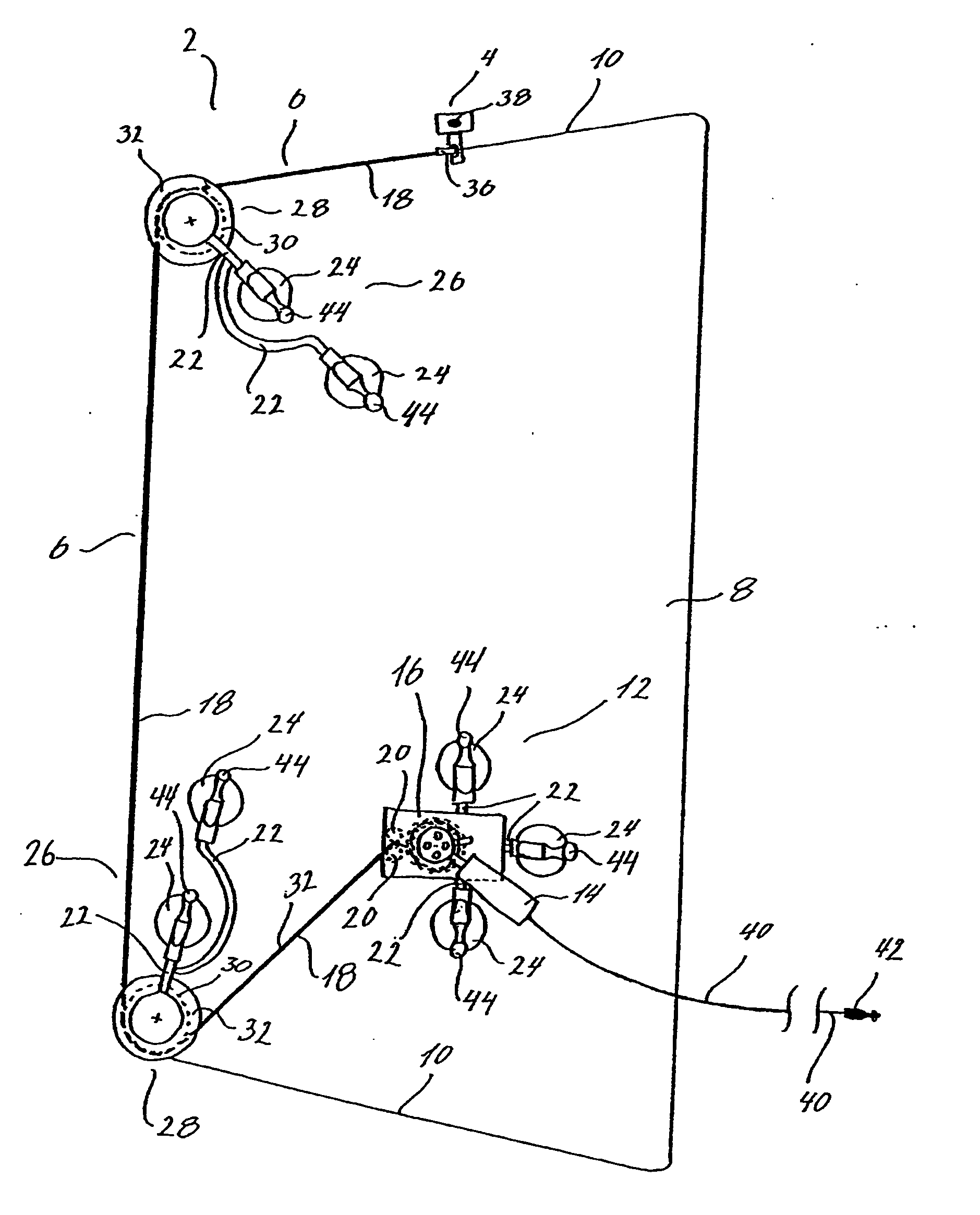
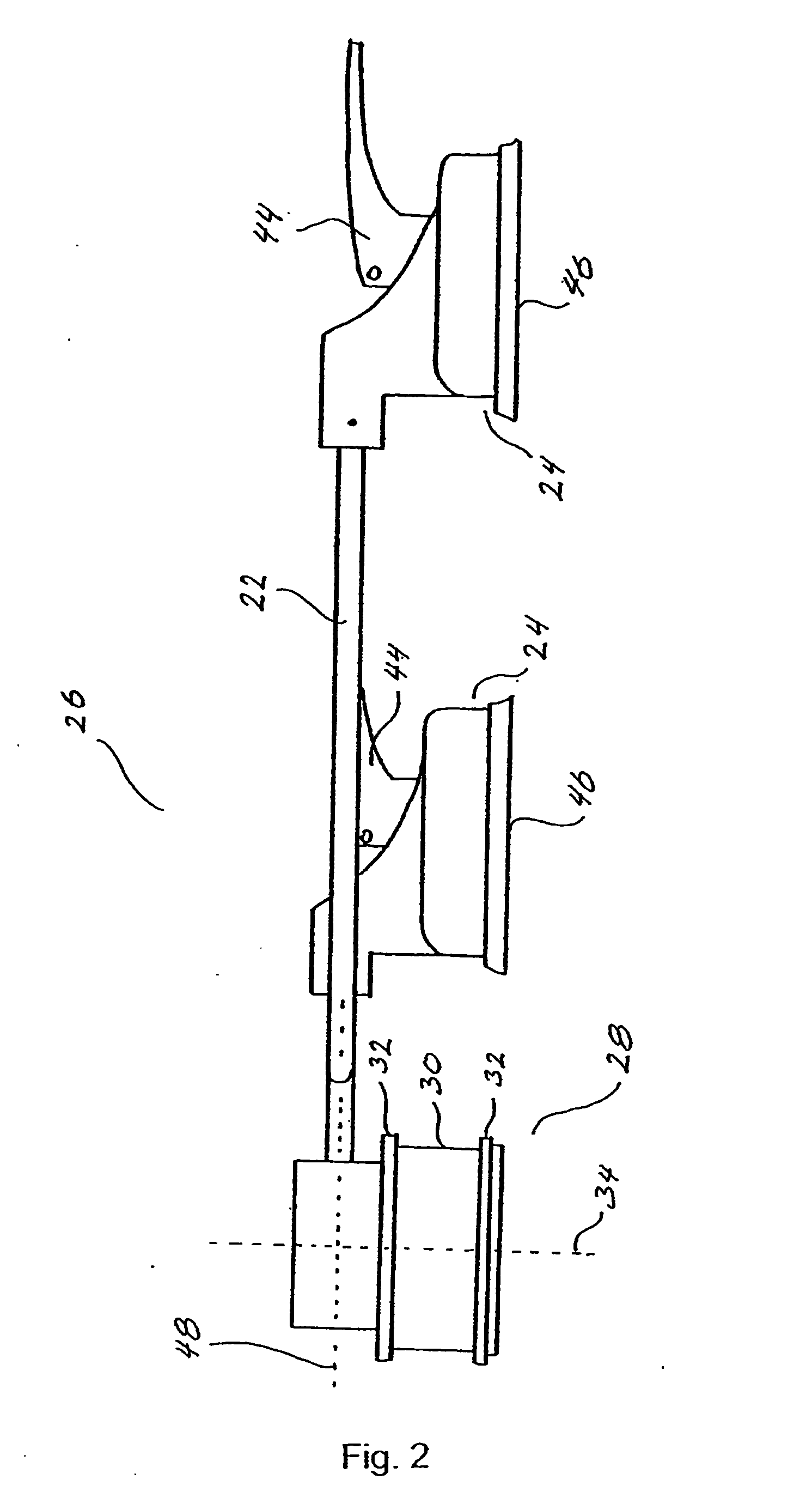
[0008] It is an object of the present invention to provide an apparatus and a method which overcome the above mentioned disadvantages. Thus the present invention relates to a tool guiding apparatus for guiding a tool along a path on a surface to be processed, said apparatus comprising:

[0009] at least one path-defining means adapted to be attached to the surface, automatic tool actuation means adapted to advance the tool along the path, wherein the automatic tool actuation means comprises a flexible force-transferring element comprising a first end and a second end, the first end being attached to the automatic tool actuation means and the second end being attached to the tool.

[0010] The tool may be guided along a plurality of straight lines but could also be guided along curves such as semicircles or a s-curve or a hyperbola or any other curve. The path may be a combination of curves and straight lines. The path defining means may be attached to the surface to be processed but cou...


PUM


Abstract

Tool guiding apparatus for guiding a tool along a path on a surface to be processed, said apparatus comprising at least one path-defining means adapted to be attached to the surface, automatic tool actuating means adapted to advance the tool along the path. Wherein the automatic tool actuation means comprises a flexible force-transferring element comprising a first end and a second end, the first end being attached to the automatic tool actuation means and the second end being attached to the tool.

Description

FIELD OF THE INVENTION [0001] The present invention relates to an apparatus for guiding a tool along a path, in particular to an apparatus for cutting a compound between a windscreen and an automobile. Furthermore, the invention relates to a method of cutting a path along a predetermined line, in particular to a method for guiding a knife along a compound between a windscreen and an automobile. BACKGROUND OF THE INVENTION [0002] Windscreens are glued to the automobile by means of a strong compound or glue. For many years car manufacturers have improved the glue so as to ensure a strong and binding connection. One reason for this is that windscreens today are load-bearing elements. Unfortunately, the windscreens need to be replaced from time to time. This is due to holes or scratches made by thrown-up pebbles. Concurrently with the improved glue or compound the windscreens are becoming harder to remove. Three general principles for removing the glue are known. The three principles ar...

Claims


Application Information

Patent Timeline
IPC IPC(8): B26B29/00B26D1/56B60J1/00
CPCB26B27/002B26D1/547B26D7/0006
Inventor JENSEN, KIM STANLEYKJAER, JAN THYBOSORENSEN, FREDDY G.SORENSEN, PALLE
Owner MOBILGLAS 2000
Why Eureka
Try Eureka