
Hybrid fiber-foam buffing pad

a hybrid foam and foam technology, applied in the field of foam hybrid foam buffing pads, can solve the problems of health hazards, wool pads are often linty, and the disadvantages of using foam pads or tufted wool pads, and achieve the effect of high speed

Inactive Publication Date: 2006-05-25
3M INNOVATIVE PROPERTIES CO
View PDF27 Cites 14 Cited by
  • Summary
  • Abstract
  • Description
  • Claims
  • Application Information

AI Technical Summary

Benefits of technology

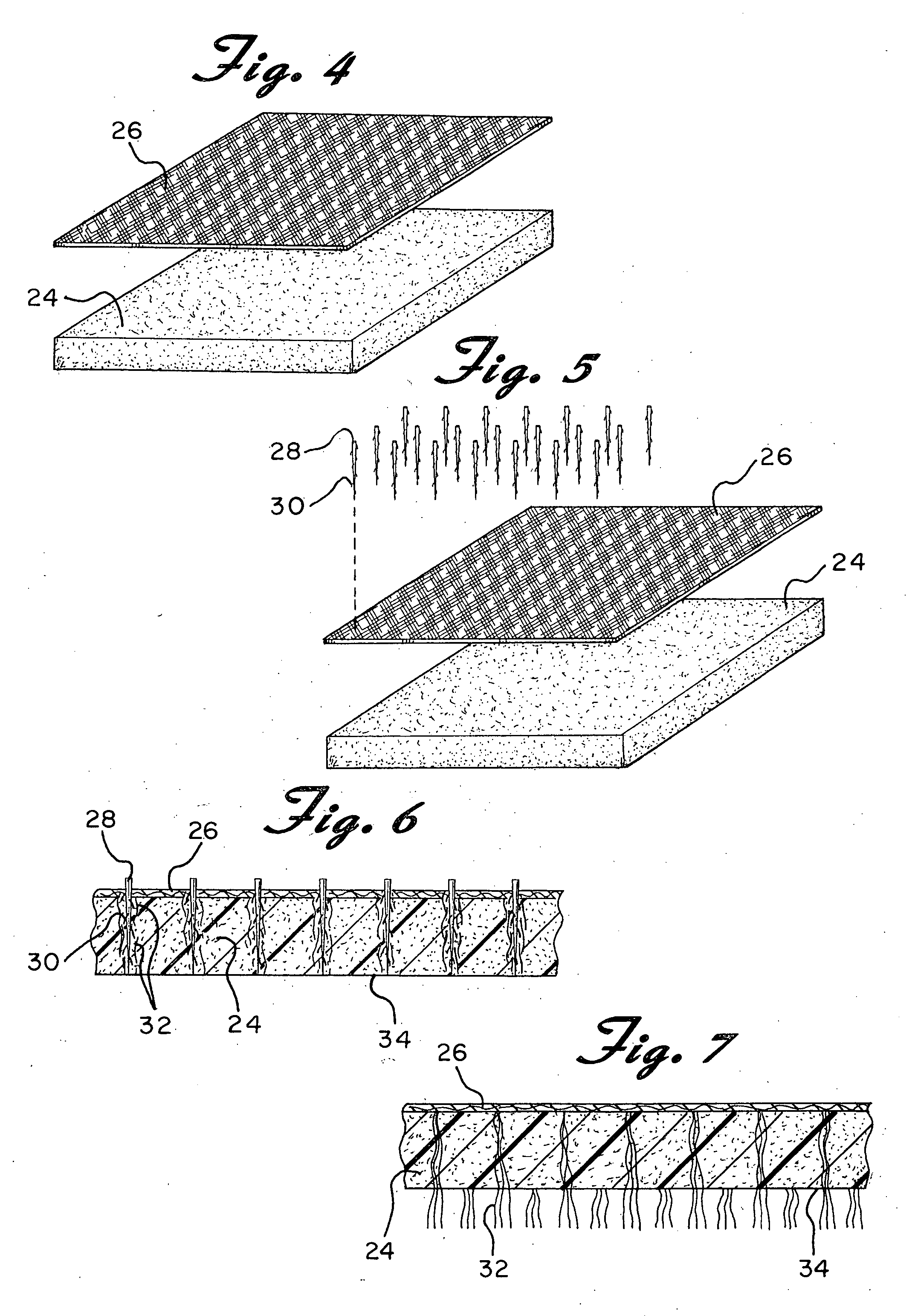
The present invention is an improved foam hybrid buffing pad for use with a rotary buffing machine for high speed polishing of various surfaces. The pad is made from a combination of foam and wool or other natural or synthetic fibers. The filaments are needle punched through the foam and can be felt fiber such as wool fiber, cotton fiber, or the like. The technical effects of this invention include improved polishing efficiency, durability, and flexibility.

Problems solved by technology

There are, however, certain disadvantages to using either the foam pads or the tufted wool pads.
For example, wool pads frequently lint.
In body shops this presents a real problem with possible paint contamination, and in a detail shop it is a nuisance and a health hazard as the airborne fibers can be inhaled.
Wool pads have become notorious with swirl marks and an inexperienced operator can easily burn paint with a wool pad.
During buffing the wool pad also can become saturated with compounds and polish becoming a flat hard surface which becomes very aggressive and can also burn the paint off the surface.
One drawback, however, is that foam pads cannot remove deep scratches, wet sand marks, and heavy oxidation as well as wool and certainly not as quickly.

Method used


Image

  • Hybrid fiber-foam buffing pad
  • Hybrid fiber-foam buffing pad
  • Hybrid fiber-foam buffing pad

Examples


Embodiment Construction

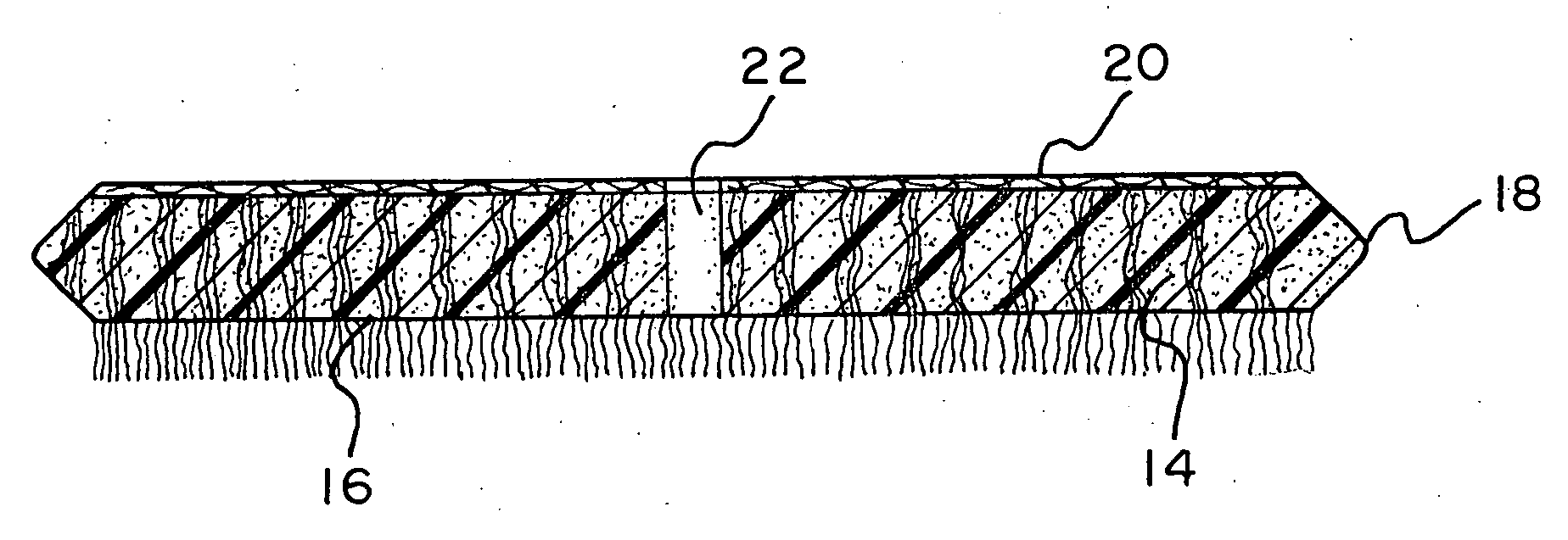
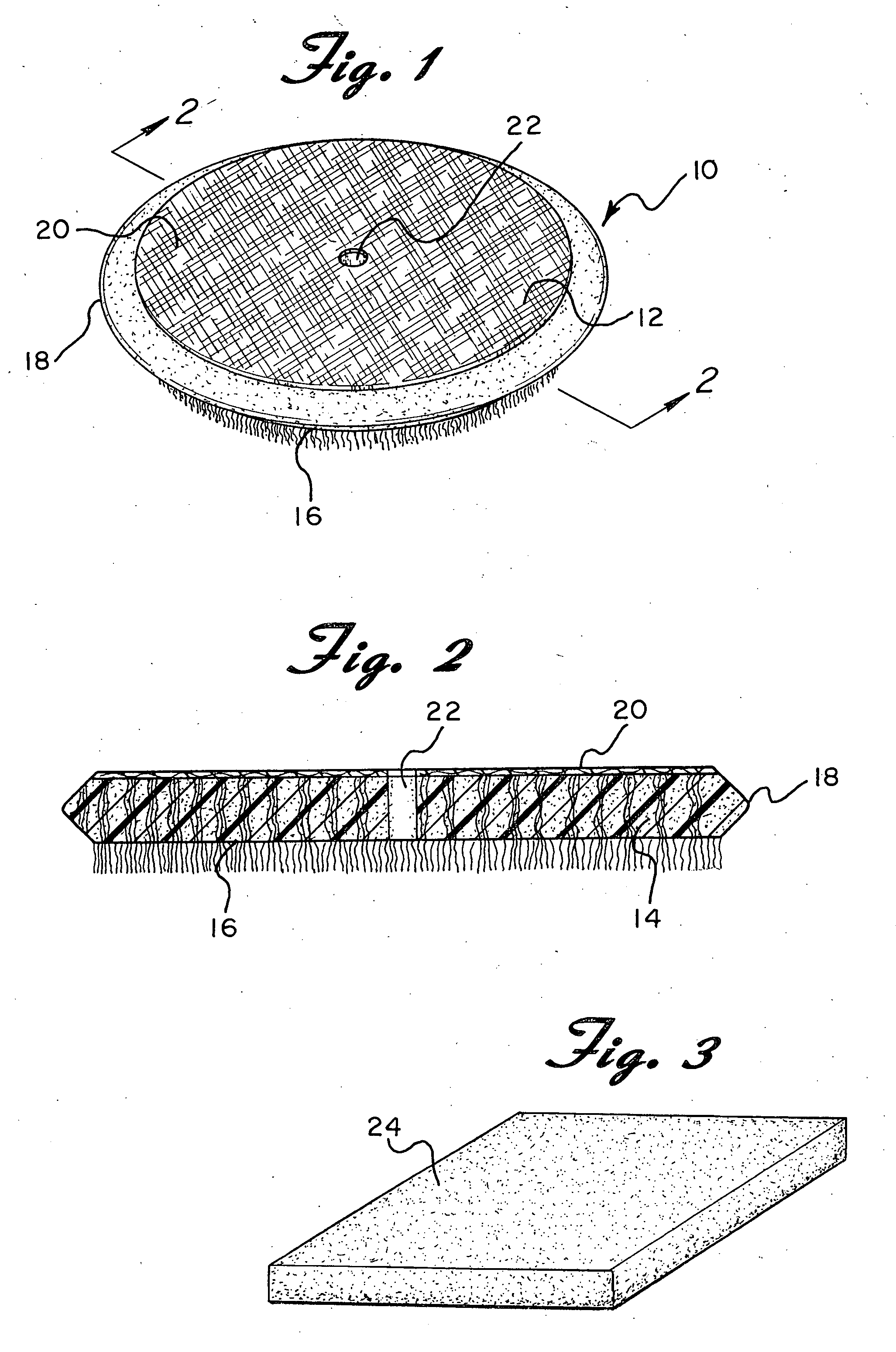
[0021] Referring now to the drawings in detail wherein like reference numerals have been used throughout the various figures to designate like elements, there is shown in FIG. 1 a buffing pad constructed in accordance with the principles of the present invention and designated generally as 10. The buffing pad 10 and may be constructed to be a single sided pad such as shown in U.S. Design Pat. No. Des. 367,743 or it may be a double sided pad with or without a quick release mechanism such as shown in U.S. Pat. No. 6,349,446. The disclosures of these two prior patents are hereby incorporated herein by reference.

[0022] In either case, the pad 10 includes a main body portion 12 which is comprised essentially of open cell foam such as shown at 14. The body portion has a front working surface 16 with an outer working edge 18 and a back surface 20. As is well known in the art, if the pad 10 is constructed to be double sided, the front and back surfaces will appear to be the same. It is pos...


PUM

PropertyMeasurementUnit
flexibleaaaaaaaaaa
densitiesaaaaaaaaaa
densityaaaaaaaaaa

Abstract

A buffing pad primarily for automobiles includes a foam layer and filaments of textile material interspersed throughout the foam layer and extending passed or exposed at the working surface of the pad. The filaments are needle punched through the foam layer. The filaments may be felt fiber such as wool fiber, cotton fiber, or the like.

Description

CROSS-REFERENCE TO RELATED APPLICATIONS [0001] This application is a Continuation of U.S. patent application Ser. No. 10 / 641,899 filed Aug. 15, 2003 which is hereby incorporated by reference.BACKGROUND OF THE INVENTION [0002] The present invention is directed toward a foam hybrid buffing pad for use with a rotary buffing machine for high speed polishing of automobiles, boats, planes, furniture, marble and other surfaces and more particularly, toward a foam buffing pad with wool or other natural or synthetic fibers interspersed throughout and extending passed or exposed at the working surface of the pad. [0003] Buffing pads for use in high speed polishing of automobiles and the like may be one-sided or two-sided. A one-sided buffing pad is typically circular and is attached to a rigid circular backing plate which is attached by a central hub to the shaft of a rotary power buffer. The pad may be permanently attached to the backing plate or releasably attached thereto in order to allow...

Claims


Application Information

Patent Timeline
Patent Type & Authority Applications(United States)
IPC IPC(8): B08B1/04
CPCB08B1/04B24D13/147D05C17/02B08B1/32
Inventor KRAUSE, AARON C.DENENBERG, SAUL D.
Owner 3M INNOVATIVE PROPERTIES CO
Learn More