
Hair curler, hair wave device using the same, and hair wave application method using such device

a hair curler and hair wave technology, applied in curling-tongs, curling irons, hair equipments, etc., can solve the problems of poor workability, large number of cords, and heavy weight of the devi

Inactive Publication Date: 2006-05-18
FUJI CORP CO LTD
View PDF6 Cites 10 Cited by
  • Summary
  • Abstract
  • Description
  • Claims
  • Application Information

AI Technical Summary

Benefits of technology

[0067] As described above, the hair curler, the hair wave device using the same, and the hair wave application method using the device according to the present invention can produce many features and advantages, as described below.

Problems solved by technology

However, since the ceramic pipe is used in the hair curler in the above-described hair wave device, the weight of the device is heavy.
Therefore, there arise problems that operation becomes cumbersome and the cord and the string cross or are entangled with each other, resulting in poor workability.
In addition, due to the heavy weight, only one hair curler is suspended from one cord, and therefore, the number of cords becomes large.
Furthermore, the above-described strings in addition to the large number of cords leads to not only a more complicated structure, but also the heavier weight of the hair curler.
When the cord or the suspending string is loosened, the weight of the hair curler is exerted directly on the head, thereby giving a pain to the client.
In contrast, if the cord or the suspending string is excessively tensed, the hair is pulled, thereby giving an unpleasant feeling to the client.
Therefore, the client must keep an original posture from beginning to end of the application in terrible distress without any freedom.
The application while preventing such entanglement markedly degrades workability in the real condition.

Method used


Image

  • Hair curler, hair wave device using the same, and hair wave application method using such device
  • Hair curler, hair wave device using the same, and hair wave application method using such device
  • Hair curler, hair wave device using the same, and hair wave application method using such device

Examples


embodiment 1

Preferred Embodiment 1

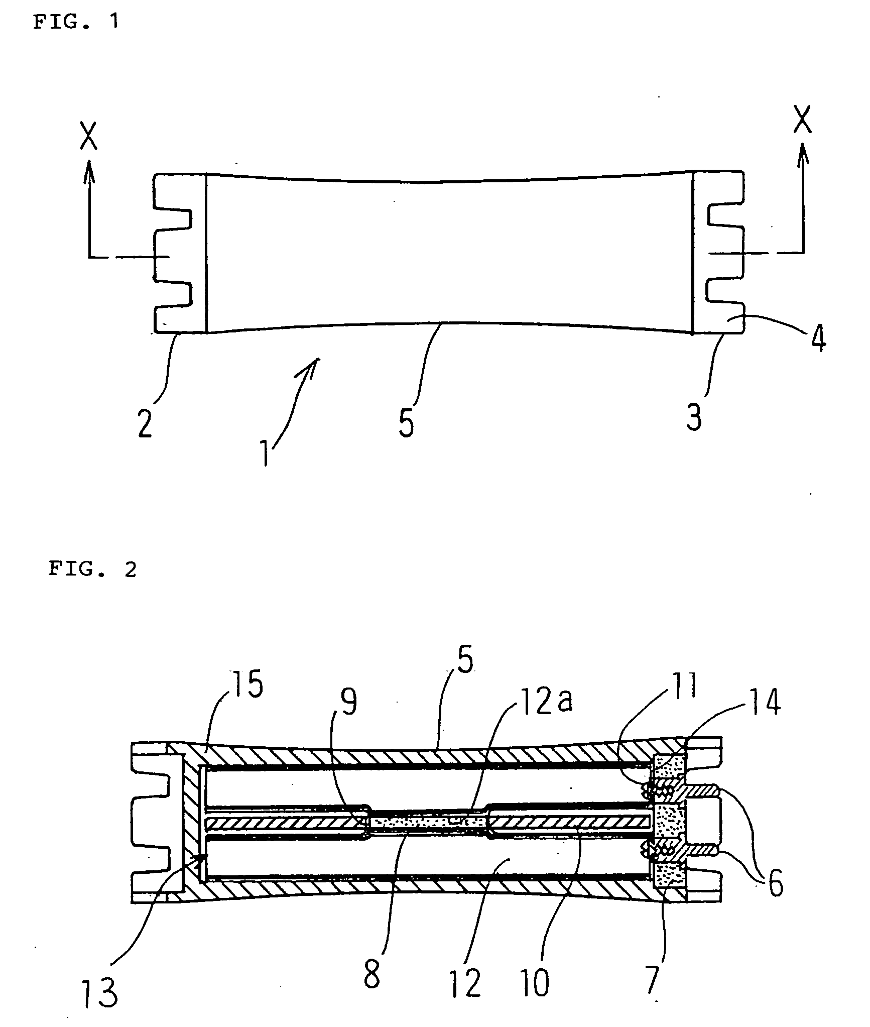
[0041] A hair curler according to the present invention will be described in a preferred embodiment in reference to FIGS. 1 to 5.

[0042]FIG. 1 is a front view showing a hair curler. A rubber band hook 4 is formed at each of a left end 2 and a right end 3 in a hair curler 1, and further, a center 5 of the hair curler 1 is formed into an arcuate shape having a reduced diameter at the center less than those at both ends.

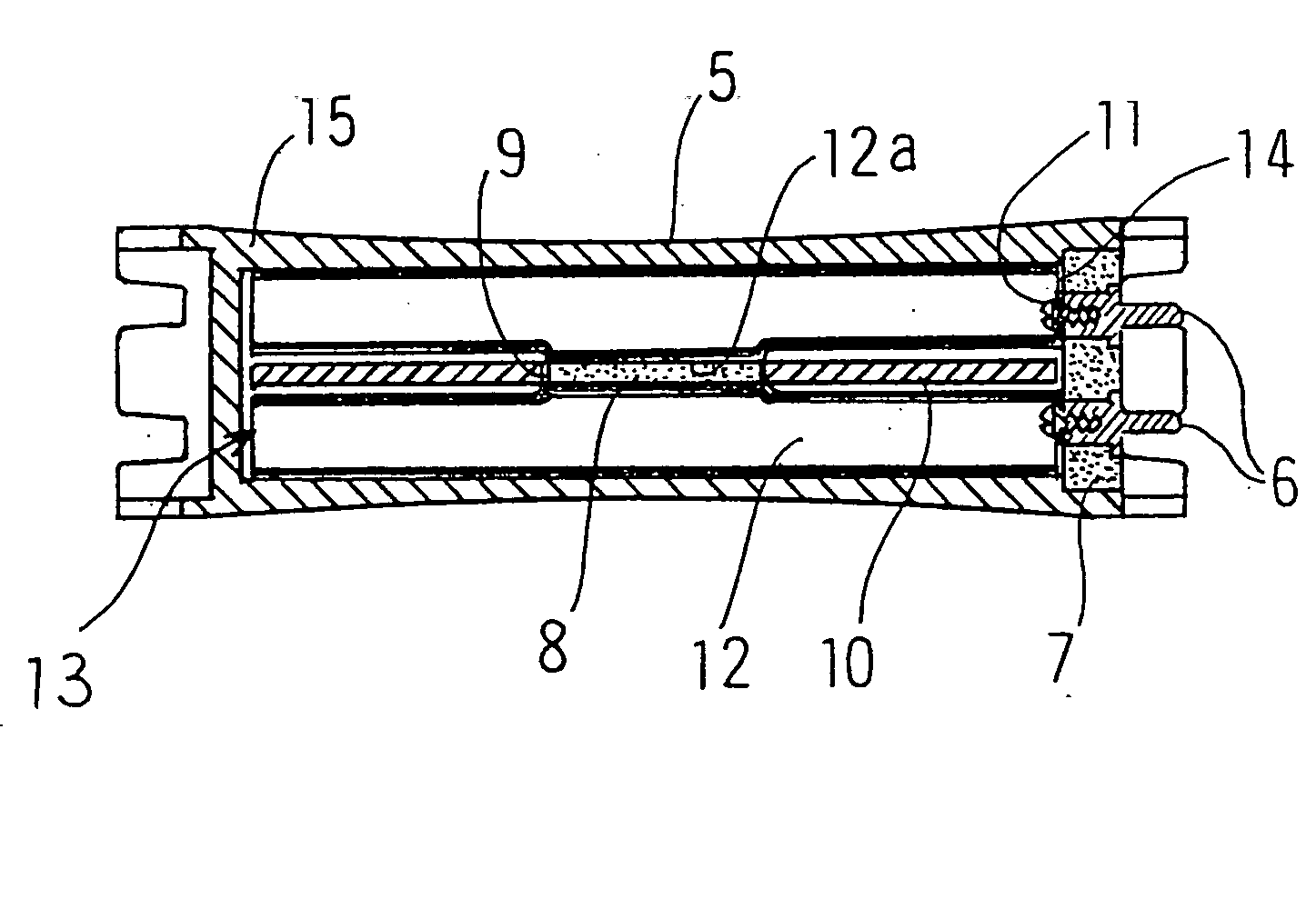
[0043] In the inside structure of the hair curler 1, as shown in FIG. 2, two terminals 6 provided for the purpose of electric connection after the hair curler 1 is set at the hair of a client are integrally planted in a cap 7 made of a heat resistant plastic by insert-molding.

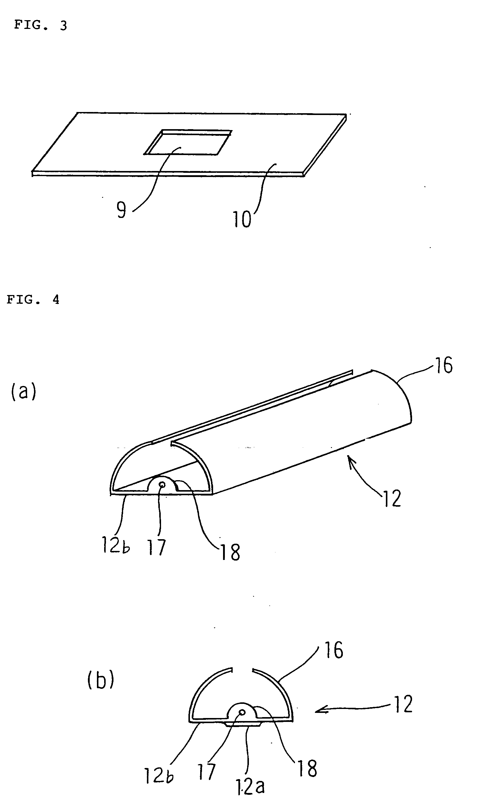
[0044] Moreover, as shown in FIG. 3, a support plate 10 made of a heat resistant plastic having an opening hole 9 for allowing a heater 8 to be fitted thereinto is interposed between the two terminals inside of the cap 7 having the terminals 6 planted therein. Additionally, ...

embodiment 2

Preferred Embodiment 2

[0054] In a hair curler 1 in a present preferred embodiment, a heating element 13 including heat conductors 12 electrically connected to a cap 7 is contained inside of a rod 15, as shown in FIGS. 6 to 8. A terminal 6 is planted outside of the cap 7, and two terminals 6a project inside of the cap 7.

[0055] In the meantime, the heat conductor 12 (which is made of copper in the present preferred embodiment) comprises: a heat conductor 12A including a plate-like member 12b having a projecting surface 12a formed at the center thereof and arcuate portions 16 bent from both ends of the plate-like member 12b and an insertion hole 20 for a fine wire (i.e., a lead wire) 19 erected from one end in a longitudinal direction and extending from the terminal 6a, and a fixing portion 18 for fixing the heat conductor 12 in abutment against the terminal 6a; and a heat conductor 12B formed into the same shape as that of the heat conductor 12A except for formation of a recessed sur...

embodiment 3

Preferred Embodiment 3

[0058] A description will be given below of a hair wave device using the hair curler described in the preferred embodiment 1 in reference to FIGS. 9 and 10.

[0059]FIG. 9 is a side view showing a hair wave device. As is clear from FIG. 9, a hair wave device 31 is configured such that a strut 32 is located eccentrically rearward of the center, a base mount 33 and a controller 34 are disposed under and above the strut 32, respectively, and at least one container 35 (two containers 35 in FIG. 9) is turnably pivoted between the base mount 33 and the controller 34. Since the container 35 is turnably pivoted on the eccentric strut, its upper portion is opened for usage by turning the container 35 when an article is put in or from the container 35. Here, the base mount 33 and the controller 34 may be fixed.

[0060] Moreover, at the rearward of the controller 34 is provided with a distributor 37 connected to a plurality of cords 36 for supplying a control electric power ...


PUM


Abstract

A hair curler is provided wherein a heating element 13 is composed of a support plate 10 formed with an opening hole 9 and installed between terminals inside a cap 7 having electric terminals 6 planted therein, a heater 8 fitted in the opening hole 9 in the support plate 10, and heat conductors 12 holding the support plate 10 supporting the heater 8 from both sides and electrically connected to the terminals 6, the heating element 13 being contained in a rod 15 made of a heat resistant plastic having an opening 14 at one end, the opening 14 being sealed by the cap 7. The hair curler is of very simple construction, which, coupled with the rod being made of a heat resistant plastic, attains weight reduction of the hair curler, thus making it possible to connect a plurality of hair curlers to a single cord and to apply waves to the client with the cord loosend and in a relaxing state.

Description

TECHNICAL FIELD [0001] The present invention relates to a hair curler, a hair wave device using the same, and a hair wave application method using the device, which are used in applying permanent waves to hair. BACKGROUND ART [0002] There has been a conventional hair wave device, in which a hair curler is disconnectably connected to one end of a cord extending from a suspended distributor box, and further, a winding drum is provided for freely putting in or out a suspending string capable of suspending the hair curler to an arbitrary position from the distributor box in the state in which the hair curler is connected to the cord, as disclosed in, for example, Japanese Patent No. 2798374. Here, the hair curler is configured such that a ceramic heater is connected to a terminal of a detachable pin jack via a lead wire, two stays are planted in a body of the pin jack in such a manner as to hold the ceramic heater between the stays, a nut is fixed to tips of the stays, a ceramic pipe is...

Claims


Application Information

Patent Timeline
Patent Type & Authority Applications(United States)
IPC IPC(8): A45D4/00A45D2/36
CPCA45D2/36A45D4/00A45D4/18
Inventor NAKAMURA, YASUE
Owner FUJI CORP CO LTD
Learn More