Ground source heat pump field design with improved control strategies

a heat pump and control strategy technology, applied in mechanical equipment, machines/engines, light and heating equipment, etc., can solve the problems of increasing the cost of energy from limited sources, high cost of geothermal energy installation or earth connection, and unattractive economic effects of geothermal systems, so as to improve control strategies and reduce drilling depths , the effect of efficient operation

Inactive Publication Date: 2006-05-18
GEOTHERMAL DESIGN GROUP
View PDF6 Cites 27 Cited by
  • Summary
  • Abstract
  • Description
  • Claims
  • Application Information

AI Technical Summary

Benefits of technology

[0005] The present invention features geothermal systems with improved control strategies for efficient operation of multiple geothermal wells. The control strategies of the present invention enable the construction of large tonnage systems which use geothermal wells with reduced drilled depths per ton. This leads to significant savings in the initial installation cost. Many of the geothermal systems of the present invention are suitable for providing continuous heating or cooling for commercial building, schools, recreational centers, or other facilities that have significant HVAC loads.
[0007] On many occasions, the geothermal system simultaneously operates a group of wells in a heat exchange phase to serve the building HVAC load, while keeping other wells deactivated for thermal recovery. The system then deactivates the group of previously active wells, while activating a group of previously inactive wells to continuously meet the building demand. This selective staging allows the system to optimize its performance and efficiency.
[0012] In many embodiments, the switching between a heat exchange phase and a thermal recovery phase for each well is coordinated through a control system. The control system can selectively activate certain well or wells to meet the immediate building HVAC load, while keeping other wells inactive for thermal recovery. The previously active well or wells are then deactivated while certain previously inactive well or wells are activated to continuously serve the building load. This alternate staging strategy is expected to maximize the overall performance and efficiency of a geothermal system of the present invention.
[0017] Any number of wells may be employed in a geothermal system of the present invention. In many embodiments, a geothermal system of the present invention includes at least 5, 10, 15, 20, 25, 30, or more wells. In many other embodiments, the center-to-center distance between each two wells is selected optimally so that there is no significant heat transfer between any two wells during seasonal use of the system. In one embodiment, the center-to-center distance from one well and its closest neighbor well is from 15 to 50 feet. However, the use of larger or shorter center-to-center distances is also contemplated by the present invention. In many cases, the field design minimizes land use, packing the wells as tightly as the thermal diffusivity of the geothermal rock will permit, so as to concentrate the stored energy to be utilized in the ensuing season.
[0019] The reduced drilled depth per ton results in decreased installation cost without compromising the large tonnage capacity of the system. In many cases, the geothermal systems of the present invention have a heat exchange capacity of at least 200, 300, 400, 500, or more tons.

Problems solved by technology

Conventional heating or cooling systems require energy from limited sources which become increasingly more expensive.
However, a major obstacle to the widespread use of geothermal energy is the high cost associated with the initial installation or earth connection.
This makes the geothermal system economically unattractive.

Method used


Image

  • Ground source heat pump field design with improved control strategies
  • Ground source heat pump field design with improved control strategies
  • Ground source heat pump field design with improved control strategies

Examples


Embodiment Construction

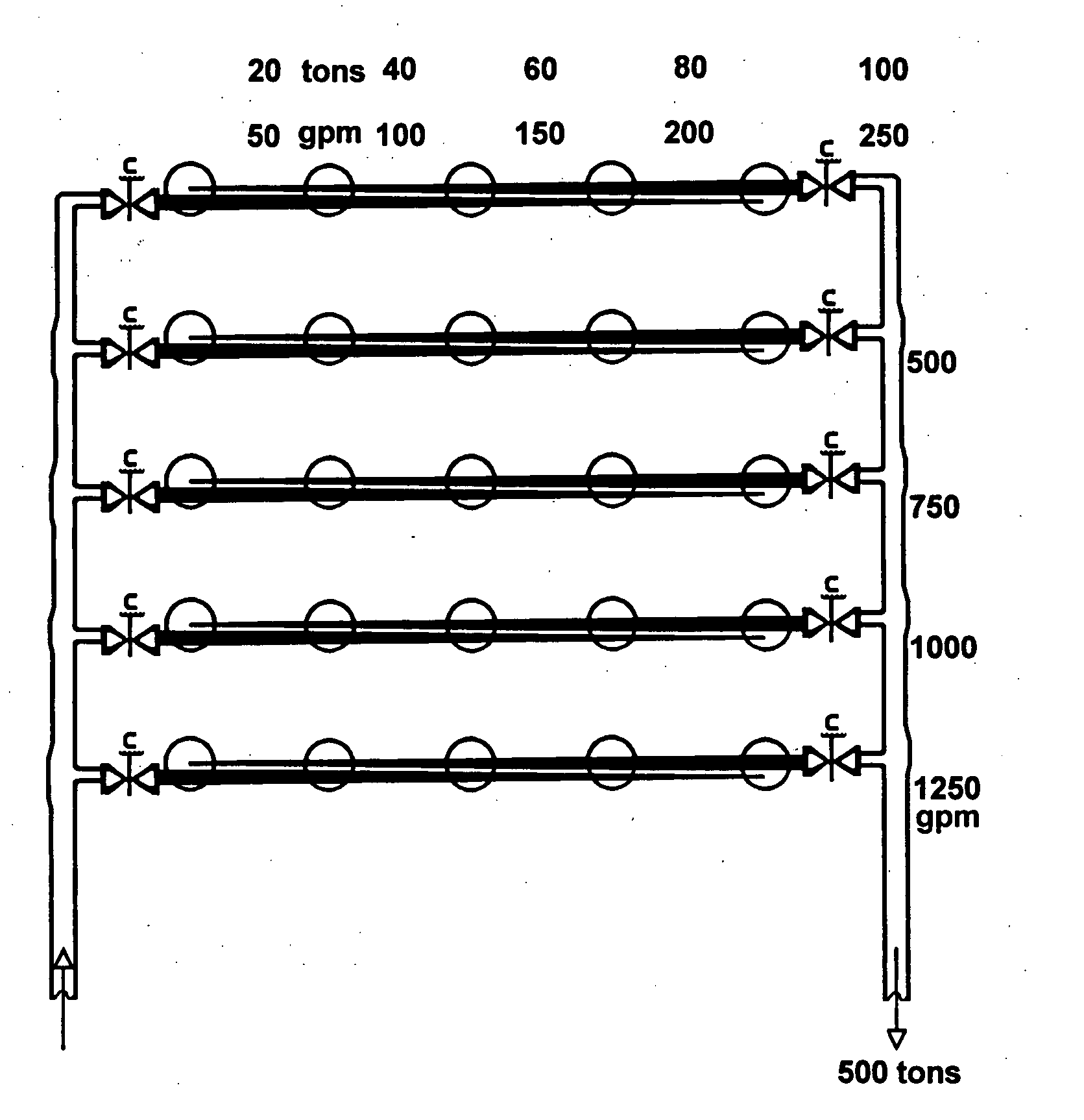
[0027] A typical geothermal system of the present invention includes two or more geothermal wells operated between the heat exchange phase and the thermal recovery phase. During a heat exchange phase, the well is engaged in exchanging heat with a heat pump or another heat exchange device. During a thermal recovery phase, the well substantially (including completely) regains thermal equilibrium with the surrounding earth. Each heat exchange stage and the subsequent thermal recovery stage constitute an operational cycle of the well. The system is capable of allowing certain wells to be actively engaged in serving the building HVAC load, while keeping other wells inactive for thermal recovery. The switching between different operational stages is regulated for each well to sustain the continuous heat exchange demand while allowing exhausted wells to have an effective thermal recovery.

[0028] In many embodiments, each well in a geothermal system of the present invention undergoes multip...


PUM


Abstract

The present invention features geothermal systems with improved control strategies for efficient operation of multiple geothermal wells. In many embodiments, each well in a geothermal system of the present invention is operated in cycles. Each cycle includes a heat exchange phase followed by a thermal recovery phase. During a heat exchange phase, the well is engaged in exchanging heat with a heat pump. During a thermal recovery phase, the well is kept inactive for establishing thermal equilibrium with the earth. On many occasions, the geothermal system simultaneously operates a group of wells in a heat exchange phase to serve the building HVAC load, while maintaining other wells inactive for thermal recovery. The switching between different operational stages is regulated for each well to improve the overall performance of the system while satisfying the building demand.

Description

[0001] The present application is a Continuation-In-Part of U.S. application Ser. No. 10 / 825,659, filed on Apr. 16, 2004, which incorporates by reference the entire disclosures of U.S. Provisional Application Ser. Nos. 60 / 463,032 and 60 / 463,033, both filed on Apr. 16, 2003.TECHNICAL FIELD [0002] The present invention relates to ground source heat pump systems with improved control strategies for efficient operation of multiple geothermal wells. BACKGROUND [0003] Conventional heating or cooling systems require energy from limited sources which become increasingly more expensive. Much attention has been given to sources of energy which exist as natural phenomena. Such energy includes geothermal energy, solar energy, tidal energy, and wind-generated energy. While all of these energy sources have advantages and disadvantages, the geothermal energy has been considered by many as most reliable, readily available, and most easily tapped. [0004] Ground water-based geothermal systems have be...

Claims


Application Information

Patent Timeline
IPC IPC(8): F03G7/00F03G7/04F24J3/08
CPCF03G7/04F24J3/08Y02E10/10F24T10/00F24T50/00F24T2010/56
Inventor KOENIG, ALBERT A.HARRELL, JAMES E.
Owner GEOTHERMAL DESIGN GROUP
Why Eureka
Try Eureka