Method of regulating resistance in a discontinuous time hot-wire anemometer
- Summary
- Abstract
- Description
- Claims
- Application Information
AI Technical Summary
Benefits of technology
Problems solved by technology
Method used
Image


Examples
Embodiment Construction
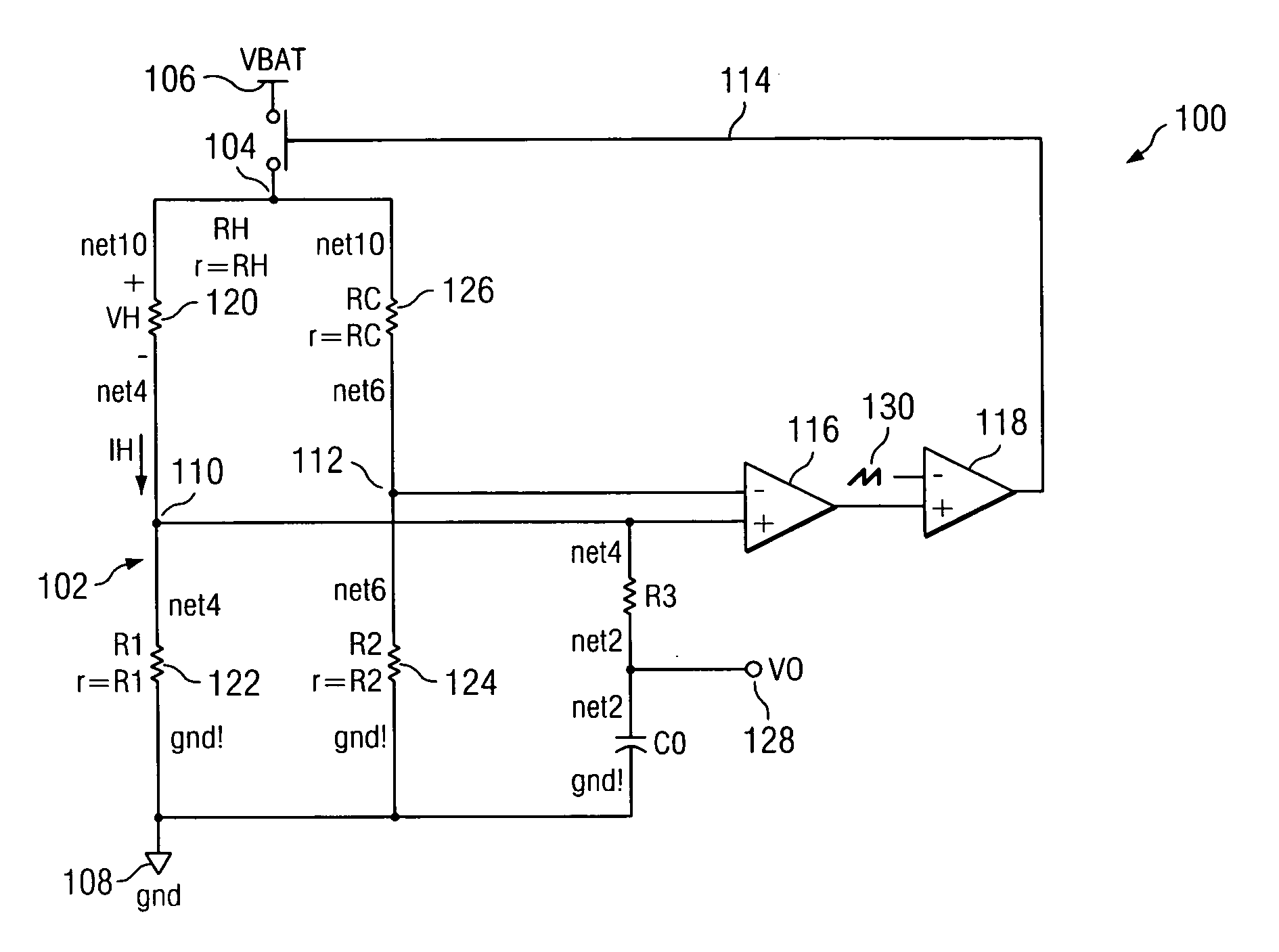
[0019] Looking now at FIG. 1, a schematic diagram illustrates a discontinuous time hot-wire anemometer 100 according to one embodiment of the present invention. It should be noted that hot-wire anemometers known in the prior art employ continuous time regulation techniques. In contradistinction, the embodiments described herein below employ discontinuous time techniques to regulate current / voltage associated with a hot-wire anemometer. The bridge circuit 102 shown in FIG. 1 is commonly termed a Wheatstone bridge. Bridge circuit 102 has a first terminal 104 connected to a voltage source 106, a second terminal connected to a reference ground 108, and a pair of output terminals 110, 112 connected to a feedback loop 114 that can be seen to include a first operational amplifier 116 and a second operational amplifier 118. The second operational amplifier 118 is employed to implement the desired discontinuous time function such that anemometer 100 power supply requirements are reduced to d...
PUM
 Abstract
Description
Claims
Application Information
 - R&D
- Intellectual Property
- Life Sciences
- Materials
- Tech Scout
- Unparalleled Data Quality
- Higher Quality Content
- 60% Fewer Hallucinations
Browse by: Latest US Patents, China's latest patents, Technical Efficacy Thesaurus, Application Domain, Technology Topic, Popular Technical Reports.
© 2025 PatSnap. All rights reserved.Legal|Privacy policy|Modern Slavery Act Transparency Statement|Sitemap|About US| Contact US: help@patsnap.com