
Vending machine with remote control alarm

Inactive Publication Date: 2006-05-11
FRAGRAMATICS MFG
View PDF7 Cites 14 Cited by
  • Summary
  • Abstract
  • Description
  • Claims
  • Application Information

AI Technical Summary

Benefits of technology

[0013] It is also a basic object is to provide a reliable alarm system ideal for car wash vending machines that sit alone in unattended, dimly lit locations that are subject to relatively high vandalism rates.
[0017] Another object is to provide a vending machine alarm that can be user-set and reset with a minimum of inconvenience.
[0018] Another object is to provide an alarm system of the character described that allows a proprietor to drive through an installation with multiple alarm-equipped machines and quickly determine the status of each.
[0023] It is also an important object to provide a vending machine of the character described that is ideally adapted for car wash installations and which is relatively easily serviced.

Problems solved by technology

Despite the advantages in security that result from specialized mounting designs, the risks of burglary and vandalism are ever-present.
Many machine components are viciously mutilated when thieves smash their way through external components trying to break into these components.
Although the burglary of money stored within vending machines is significant, the cost of physical damages inflicted upon vending machine structures by thieves during a theft often exceeds the amount of money stolen.
However, known alarms suffer from many disadvantages.
Usually burglars try to pry open the vending machine door with a crow bar or other large lever, the use of which results in significant damages.
However, if the burglar or vandal is attempting to pry open the door at a point below the latch, and if the alarm switch is above the latch, the alarm may not be triggered.
Many alarms require constant attention and complex maintenance by the proprietor.
Some alarms are simply too difficult to set and reset.
Most importantly, many common systems are prone to frequent, irritating false alarms.

Method used


Image

  • Vending machine with remote control alarm
  • Vending machine with remote control alarm
  • Vending machine with remote control alarm

Examples


Embodiment Construction

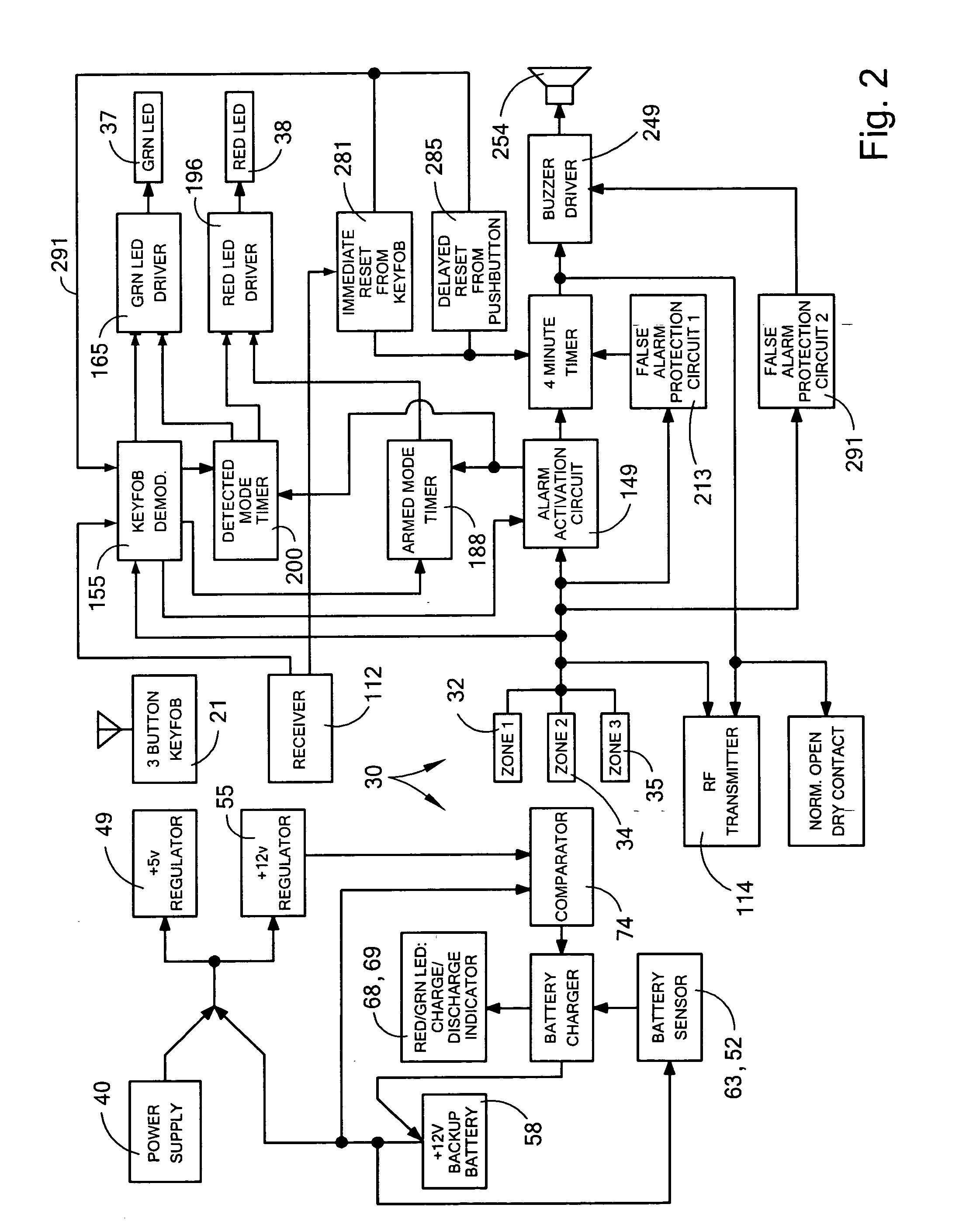
[0036] With initial reference now directed to FIGS. 1 and 2 of the appended drawings, the preferred vending machine has been generally designated by the reference numeral 10. It will be appreciated at the onset that the vending machine may be employed to vend a variety of products, and it may include a variety of internal parts, shelves, dispenser arrangements, coin-acceptors, dollar-bill acceptors or other typical accessories and features that are known to those skilled in the art. Vending machine 10 comprises a rigid, upright, cabinet 11 preferably made of stainless steel. The cabinet is normally disposed upon a suitable supporting surface 17 (FIG. 1), which preferably is provided by a suitable, elevated outdoor pedestal mounting of conventional design. Plumbing and electrical connections necessary for vending machines of this genre will be available proximate the mounting island, and often they are wired through the island into the interior volume 16 of the vending machine, as re...


PUM


Abstract

An electronic alarm and a vending machine equipped with the alarm monitors a plurality of zones by suitable circuitry to detect vandalism and theft. Each zone has a mechanically-triggered sensor that provides an electrical output. The zones comprise a pair of door sensors and a separate, shock sensor. A solid-state logic circuit includes a red and green indicator light, and a loud warning buzzer ultimately triggered by the sensors. A circuit time delay and logic scheme analyzes sensor status, and separate false-alarm prevention circuits insure proper triggering after a predetermined delay. Alarm status is indicated by highly visible green and red status lights mounted on the door. A buzzer sounds in response to sensor activation and circuit logic. A back-up battery that is coupled to the logic circuitry for fail-safe operation includes an automatic recharge system, and dual red and green LED's monitor battery condition.

Description

BACKGROUND OF THE INVENTION [0001] 1. Field of the Invention [0002] The present invention relates generally to vending machine alarm systems. More particularly, the present invention relates to alarm-equipped vending machines typically used at self-service car washes that are deployed in unattended locations, and which are subject to relatively high rates of vandalism and theft. [0003] 2. Description of the Related Art [0004] Over the last several years, the self-service car wash industry has greatly modified the quality and quantity of products and services that are offered to customers. Many ancillary products such as vehicle waxes, detergents and other diverse items are sold from self-service “coin-operated” vending machines of diverse sizes, configurations and shapes that are usually mounted conveniently close to the washing bays. (As used herein the term “coin-operated” refers to self service vending machines that accept coins, credit cards, currency, tokens, or combinations th...

Claims


Application Information

Patent Timeline
IPC IPC(8): G08B13/14G08B19/00G08B13/08G08B13/00
CPCG07F9/02G08B7/06G08B13/08G08B13/1436
Inventor INGRAM, JAMES LARRYFUNDYLER, YEFIM Y.GOODWIN, TONY M.
Owner FRAGRAMATICS MFG
Learn More