X-ray imaging apparatus
a technology of x-ray imaging and x-ray, which is applied in the direction of radiological control devices, instruments, television systems, etc., can solve the problems of inability to bring patients, difficulty in compacting and lightweight electronic cassettes, and increasing the size and weight of electronic cassettes, etc., to achieve the effect of improving the connectability of cables
- Summary
- Abstract
- Description
- Claims
- Application Information
AI Technical Summary
Benefits of technology
Problems solved by technology
Method used
Image
Examples
first embodiment
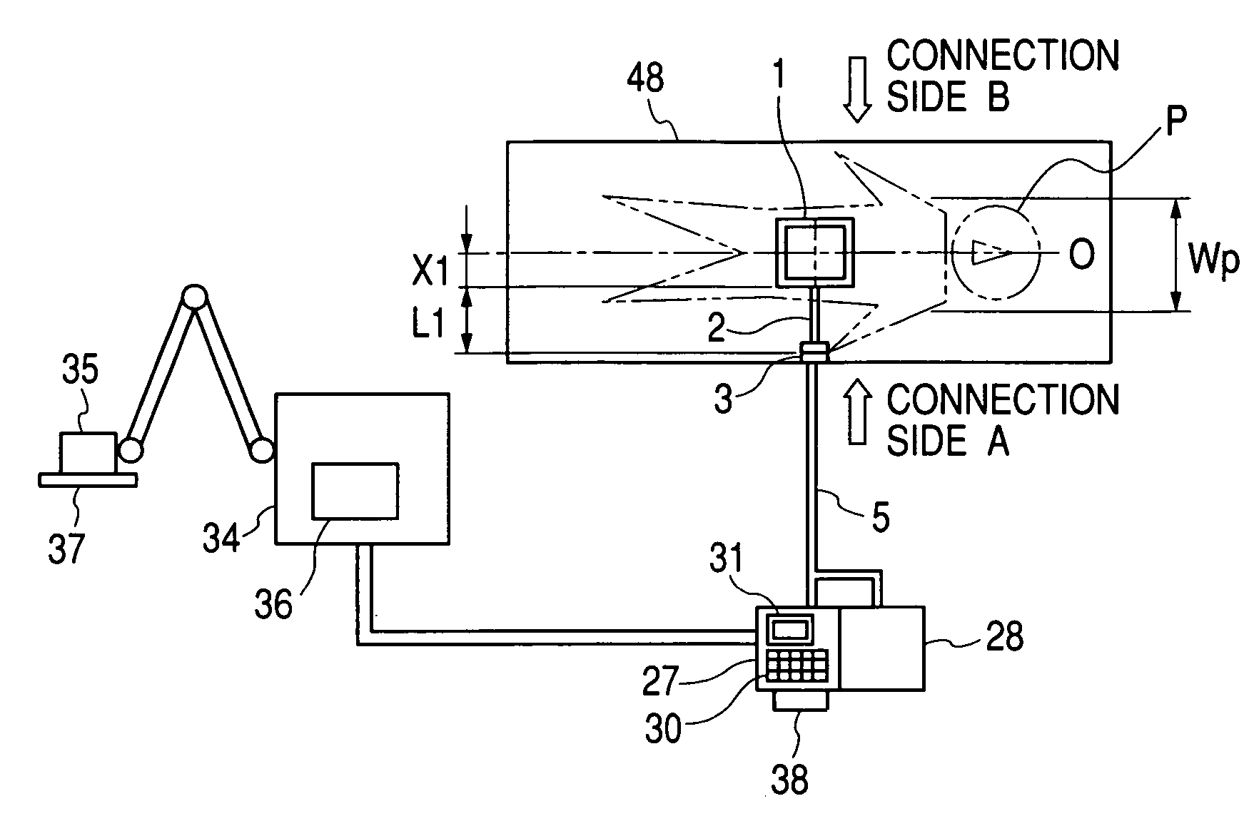
[0041]FIGS. 1A and 1B are diagrams showing the structure of a Parts equivalent to those in the previously mentioned drawings will be designated by the same reference characters.
[0042] What is different in this embodiment from the electronic cassette 49 shown in FIG. 6 is that a cable 2 is connected to the case of an electronic cassette 1 and a connector 3 is provided at the end of the cable 2. In FIG. 1B, L1 represents the distance from the side surface of the electronic cassette 1 to which the cable 2 is connected to the end of the cable 3, and X1 represents the distance from the center C of the imaging area 4 of the electronic cassette 1 to the aforementioned side surface of the electronic cassette 1. The electronic cassette 1 has a connection port for the cable 2 provided on the aforementioned side surface. In FIG. 1A, Wp represents the shoulder width or the maximum body width defined by Japanese Industrial Standards (JIS) Z8500 (directed to measurement of human body), and line ...
second embodiment
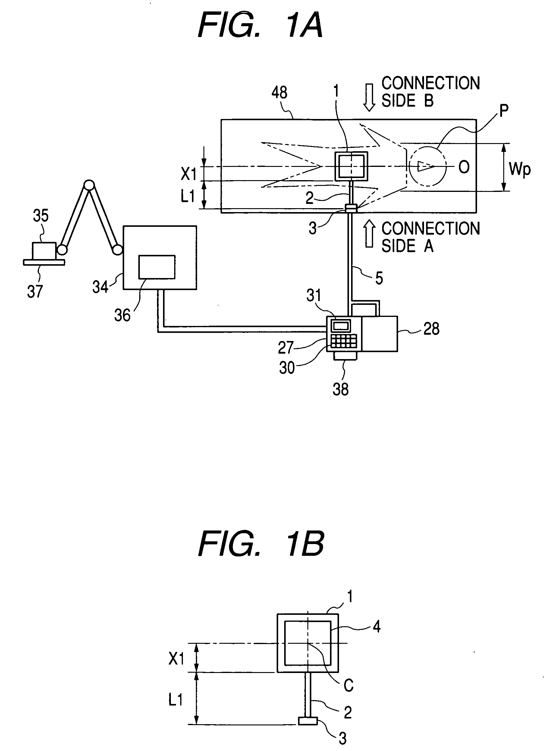
[0046]FIG. 2 is a diagram showing the structure of the present invention. In FIG. 2, the parts same as those in the previously mentioned drawings are designated by the same reference characters.
[0047] What is different in this embodiment from the electronic cassette 1 shown in FIGS. 1A and 1B is that the electronic cassette has a substantially rectangular shape, the connection port for a cable 7 is provided on a long side of it, and a connector 8 is provided at the end of the cable 7. The imaging area 9 also has a substantially rectangular shape. In the situation shown in FIG. 2, the electronic cassette 6 is disposed in such a way that its long side is perpendicular to the center line of the body axis O of the patient P. Therefore, the connection port for the cable 7 can hardly be visually observed, since it is beneath the body of the patient P. However, letting L2 be the distance from the side surface of the electronic cassette 6 to which the cable 7 is connected to the end of the ...
third embodiment
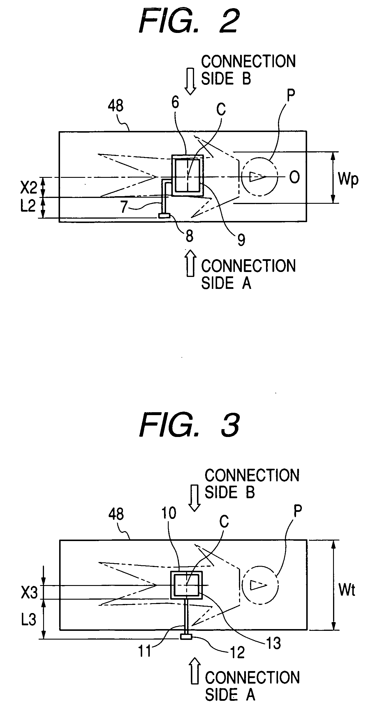
[0049]FIG. 3 is a diagram showing the structure of the present invention. In FIG. 3, the parts same as those in the previously mentioned drawings are designated by the same reference characters.
[0050] What is different in this embodiment from the electronic cassette 49 shown in FIG. 6 is that a cable 11 is connected to the case of an electronic cassette 10 and a connector 12 is provided at the end of the cable 11. In FIG. 3, L3 represents the distance from the side surface of the electronic cassette 10 facing the connection side A to the end of the cable 12, and X3 represents the distance from the center C of the imaging area 13 of the electronic cassette 10 to the aforementioned side surface of the electronic cassette 10. The electronic cassette 10 has a connection port for the cable 11 provided on the aforementioned side surface. In addition, Wt represents the width of the bed 48. Specifically, the width Wt represents the width of the bed 48 in the direction perpendicular to the b...
PUM
 Abstract
Description
Claims
Application Information
 - R&D
- Intellectual Property
- Life Sciences
- Materials
- Tech Scout
- Unparalleled Data Quality
- Higher Quality Content
- 60% Fewer Hallucinations
Browse by: Latest US Patents, China's latest patents, Technical Efficacy Thesaurus, Application Domain, Technology Topic, Popular Technical Reports.
© 2025 PatSnap. All rights reserved.Legal|Privacy policy|Modern Slavery Act Transparency Statement|Sitemap|About US| Contact US: help@patsnap.com


