
Cooling air flow passage of refrigerator

Active Publication Date: 2006-05-11
LG ELECTRONICS INC
View PDF11 Cites 47 Cited by
  • Summary
  • Abstract
  • Description
  • Claims
  • Application Information

AI Technical Summary

Benefits of technology

[0011] An object of the present invention is to provide a cooling air flow passage of a refrigerator, capable of increasing the energy efficiency of the refrigerator by simplifying the structure and reducing the length of the passage.
[0012] Another object of the present invention is to provide a cooling air flow passage of a refrigerator, capable of making structure of the refrigerator small by adopting simplified cooling air flow passages.
[0013] A further another object of the present invention is to provide a cooling air flow passage of a refrigerator, capable of simplifying the structure of the refrigerator and reducing manufacturing costs by incorporating the ice making unit and the water tank into a single unit, thereby reducing the length of the cooling air flow passage.
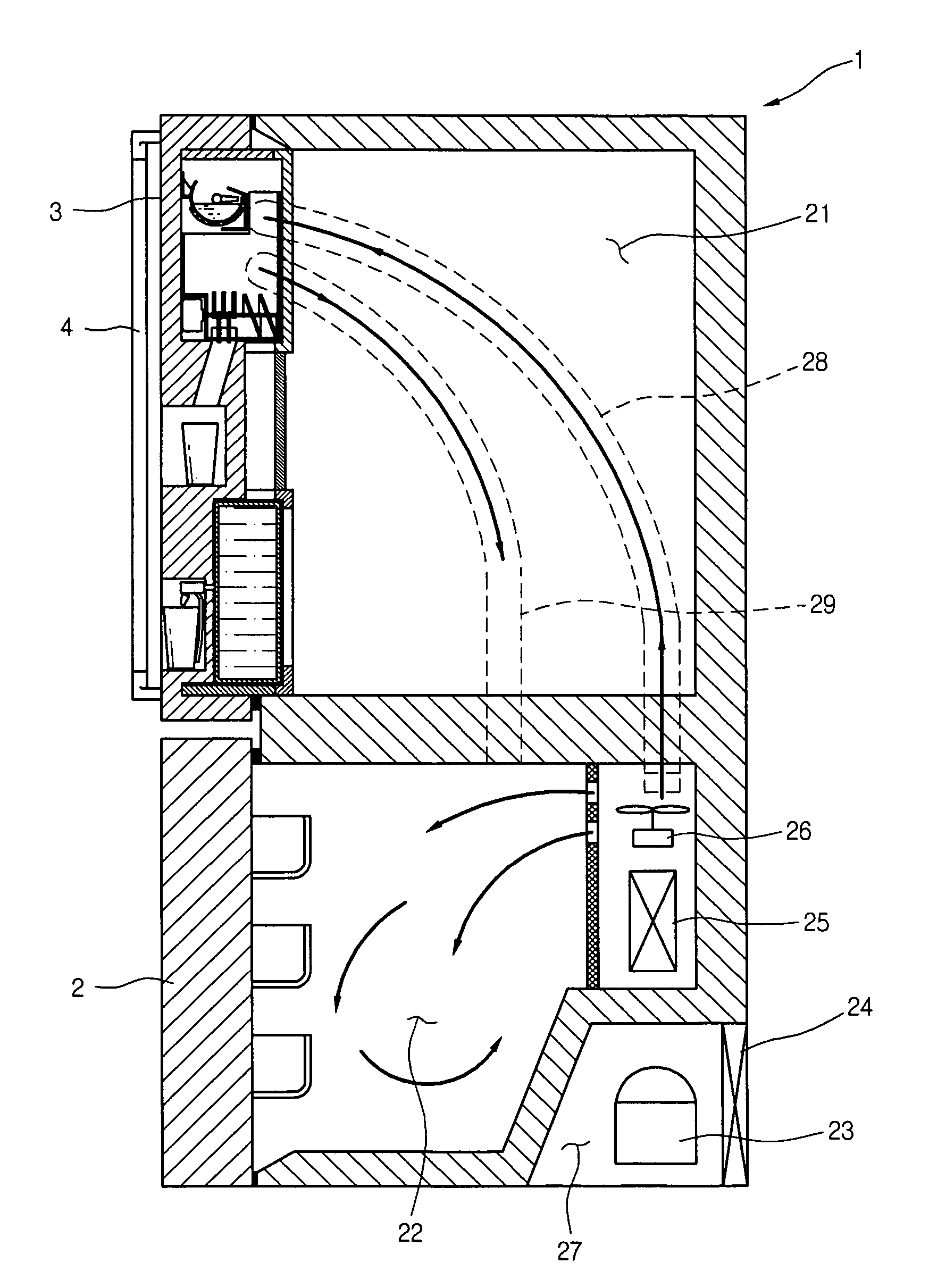
[0018] According to the cooling air flow passage for the refrigerator, both the ice making unit and the water dispensing unit can be simultaneously operated by the cooling air supplied through the single cooling air flow passage. Because a separate passage for supplying cooling air to the water dispensing apparatus is not needed, the overall length of the passage can be shortened, the efficiency of the refrigerator is increased, the structure of the refrigerator is simplified, the refrigerator's structure is made smaller, and thus the manufacturing cost is reduced.

Problems solved by technology

However, since separate cooling air flow passages are needed to supply the cooling air that has been cooled in an evaporator to an ice making unit and a water dispenser according to the prior art, the structure of the cooling air flow passages in a refrigerator is complicated.
Furthermore, since the structure of the cooling air flow passages are complicated, the thickness of a refrigerator's walls increases, thereby reducing the area available for foodstuff storage and thus increasing the overall size of the refrigerator.
Also, because of the complications of the cooling air flow passage's structure, cooling air loss is increased during transfer of the cooling air and resultantly energy efficiency is deteriorated.
Moreover, when a refrigerator employs separate rooms for refrigerating and freezing, and an ice making unit and a water tank are built inside the refrigerating room, the problems of reduced storage space and increased cooling air loss become severe.

Method used


Image

  • Cooling air flow passage of refrigerator
  • Cooling air flow passage of refrigerator
  • Cooling air flow passage of refrigerator

Examples


Embodiment Construction

[0027] Reference will now be made in detail to the preferred embodiments of the present invention, examples of which are illustrated in the accompanying drawings.

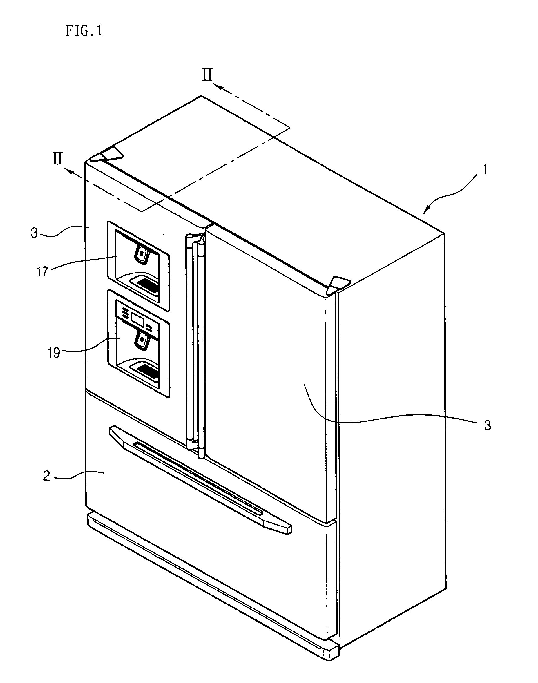
[0028]FIG. 1 illustrates a bottom freezer-type refrigerator (in which refrigerating rooms are located in the top portion and the freezing rooms are located in the bottom portion) to which the present invention can be applied.

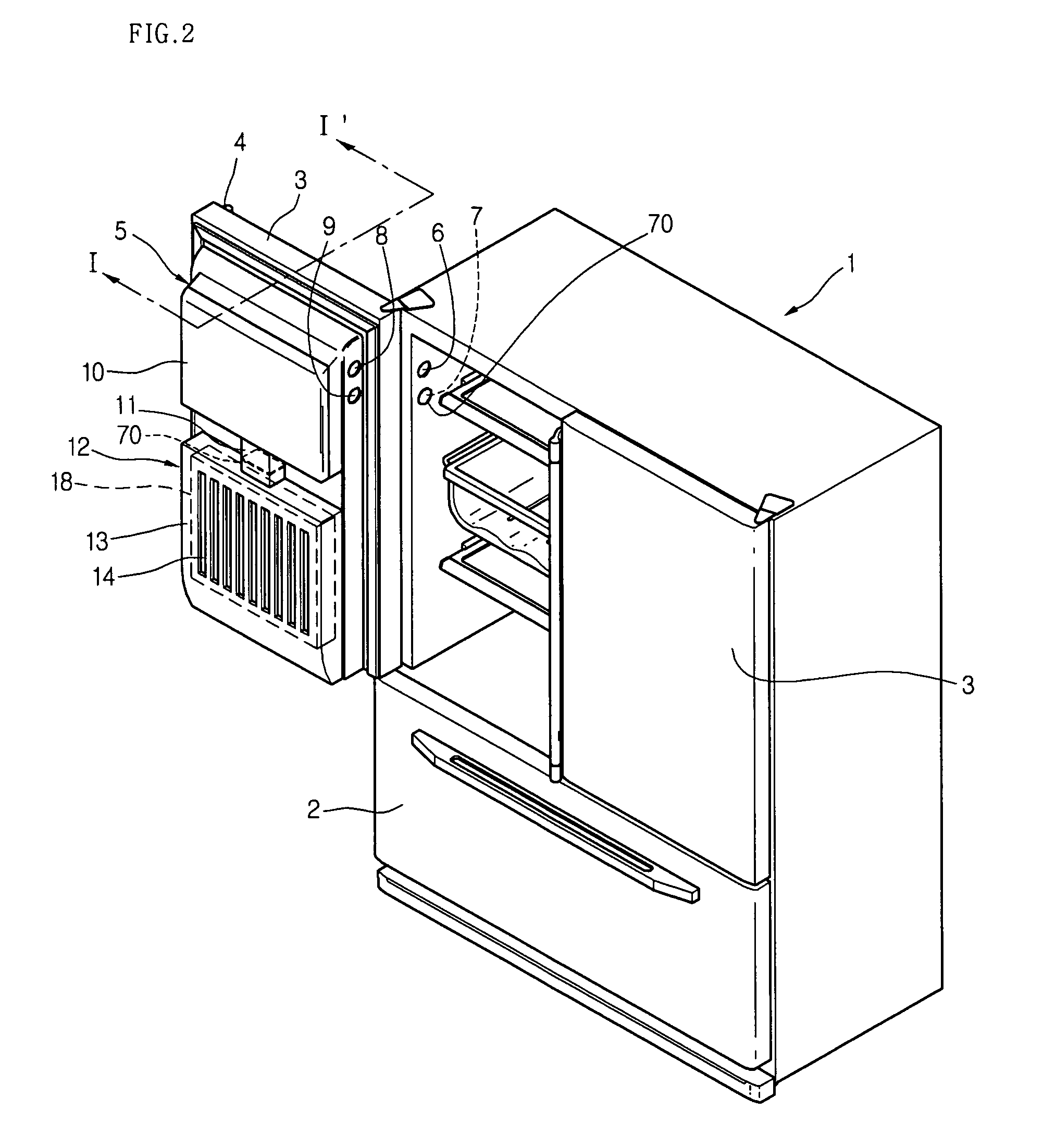
[0029] On the main body of a refrigerator 1, a freezing room door 2 is located at the bottom and a refrigerating room door 3 is located at the top. Furthermore, an ice dispenser 17 for dispensing ice and a water dispenser 19 for dispensing at least cold water are located on the front portion of the refrigerating room door 3. As illustrated, the ice and water dispensers can be separated and can constitute a single unit. Further, ice or water can be selectively supplied by pressing a predetermined button depending on user's demand. Description will be made below on the assumption that the ice and the wa...


PUM


Abstract

A cooling air flow passage of a refrigerator is provided. The cooling air not only flows through the passage so as to make ice in an ice making chamber but is also sent so as to cool water in a water storage tank. Therefore, the cooling air flow passage of the refrigerator and the overall structure of the refrigerator are simplified, which increases the efficiency of the refrigerator and reduces the manufacturing cost.

Description

BACKGROUND OF THE INVENTION [0001] 1. Field of the Invention [0002] The present invention relates to a refrigerator, and more particularly, to a cooling air flow passage in a refrigerator. Still more particularly, the present invention relates to a cooling air flow passage of a refrigerator capable of improving the operational efficiency and simplifying the structure of the refrigerator by allowing cooling air to be efficiently supplied to and used at an ice making unit. [0003] 2. Description of the Related Art [0004] An ice making unit for making ice is attached to the inside of a refrigerator and makes ice of an adequate size for providing to a user. Also, as users' tastes are recently becoming more luxury-oriented, there is an increasing trend for a refrigerator to have a built-in type ice maker mounted to its in side. [0005] Furthermore, a refrigerator has a self-contained water dispensing passage for allowing water that is obtained from an outside source to be cooled and dispen...

Claims


Application Information

Patent Timeline
IPC IPC(8): F25C1/00F25D17/04
CPCF25C1/00F25C5/005F25D17/06F25D23/04F25D23/126F25D2317/062F25D2323/122F25D2400/04F25D2400/06F25C5/22F25C1/24F25D17/08
Inventor LEE, WOOK YONG
Owner LG ELECTRONICS INC
Learn More