Eureka AIR delivers breakthrough ideas for toughest innovation challenges, trusted by R&D personnel around the world.

Golf club head with variable flexural stiffness for controlled ball flight and trajectory

a golf club and variable flexural stiffness technology, applied in the field of golf club heads, can solve the problems of high dependence on the accuracy of conventional clubs, environmental effects that are beyond the control of golf equipment manufacturers, etc., and achieve the effect of high ball velocity

Inactive Publication Date: 2006-05-04
ACUSHNET CO
View PDF15 Cites 60 Cited by
  • Summary
  • Abstract
  • Description
  • Claims
  • Application Information

AI Technical Summary

Benefits of technology

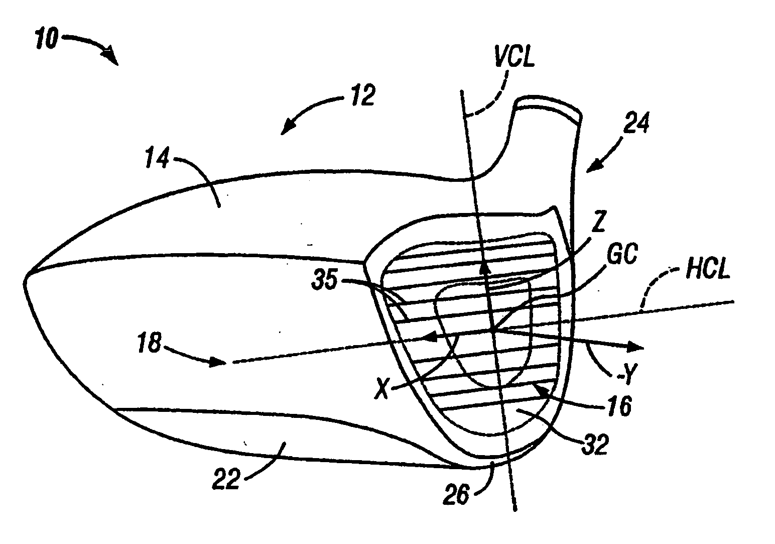
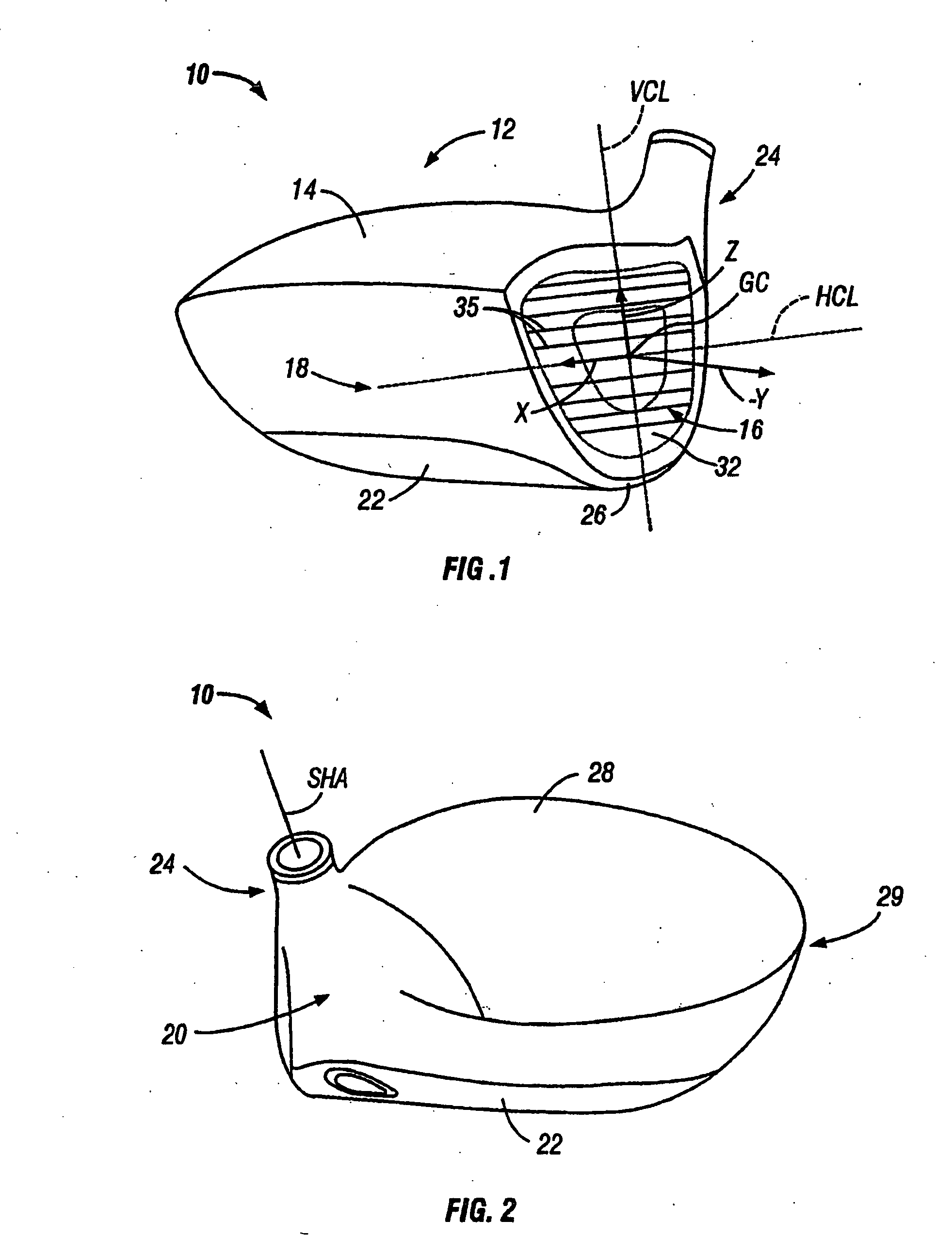
[0012] The present invention relates to a golf club head adapted for attachment to a shaft. The head includes a face and a body. The face is configured and dimensioned so that it includes a central portion and an adjacent surrounding intermediate portion. The central portion is relatively rigid and the intermediate portion is relatively flexible so that upon ball impact, the intermediate portion of the face deforms to provide high ball velocity, while the central portion is substantially un-deformed so that the ball flies on-target. Thus, upon ball impact the deformation of the intermediate portion allows the central region to move into and out of the club head as a unit. As a result, the head exhibits a coefficient of restitution greater than 0.81.

Problems solved by technology

However, these environmental effects are beyond the control of the golf equipment manufacturer.
Furthermore, the accuracy of conventional clubs is highly dependent on impact location.

Method used


Image

  • Golf club head with variable flexural stiffness for controlled ball flight and trajectory
  • Golf club head with variable flexural stiffness for controlled ball flight and trajectory
  • Golf club head with variable flexural stiffness for controlled ball flight and trajectory

Examples


examples

[0072] These and other aspects of the present invention may be more fully understood with reference to the following non-limiting examples, which are merely illustrative of embodiments of the present invention golf club head, and are not to be construed as limiting the invention, the scope of which is defined by the appended claims.

TABLE 1FLEXURAL STIFFNESS INFORMATIONComparativeComparativeComparativeInventiveParameterExample 1Example 2Example 3ExampleThickness of Center Zone0.1150.1300.0950.150(inches)Thickness of First0.1150.1000.0980.075Intermediate Zone (inches)Thickness of Second0.1150.0800.1000.075Intermediate Zone (inches)Thickness of Perimeter0.1150.1500.1200.120Portion (inches)E of All Portions (psi)1.65E+071.65E+071.65E+071.65E+07FS of Center Portion25094362511414755688(lb-in)FS of First Intermediate2509416500155306961zone (lb-in)FS of Second Intermediate250948448165006961Zone (lb-in)FS of Perimeter Zone25094556882851228512(lb-in)FS1 / FS21.02.20.98.0FS3 / FS21.03.41.84.1

[00...


PUM

PropertyMeasurementUnit
thicknessaaaaaaaaaa
velocityaaaaaaaaaa
velocityaaaaaaaaaa

Abstract

The present invention relates to a golf club head with a hitting face. The hitting face comprises a directional control portion, which has at least two zones with different flexural stiffness, such that when the hitting face strikes a golf ball the two zones deform differently to selectively control the direction of the flight of the golf ball. The directional control portion may comprise an upper zone and a lower zone, where the upper zone has a lower flexural stiffness. Alternatively, the lower zone has a lower flexural stiffness. On the other hand, the directional control portion may comprise a left zone and a right zone, and either the left or right zone may have a lower flexural stiffness to selectively control the lateral launch angle either to the left of right. The hitting face may further comprise a central zone disposed within the directional control zone, wherein the central zone has a flexural stiffness of at least about three times greater than the flexural stiffness of the directional control zone.

Description

CROSS-REFERENCE TO RELATED APPLICATION [0001] The present application is a divisional application of co-pending U.S. patent application No. 10 / 428,051 filed May 1, 2003, which is a continuation-in-part of co-pending U.S. patent application No. 09 / 551,771 filed on Apr. 18, 2000, now U.S. Pat. No. 6,605,007. The parent patent applications are incorporated herein in their entirety.FIELD OF THE INVENTION [0002] The invention is an improved golf club head. More particularly, the invention is a golf club head with an improved striking face having discrete zones with varying flexural stiffness, improved accuracy, and a high coefficient of restitution. BACKGROUND OF THE INVENTION [0003] The complexities of golf club design are well-known. The specifications for each component of the club (i.e., the club head, shaft, hosel, grip, and subcomponents thereof) directly impact the performance of the club. Thus, by varying the design specifications, a golf club can be tailored to have specific per...

Claims


Application Information

Patent Timeline
Patent Type & Authority Applications(United States)
IPC IPC(8): A63B53/04A63B53/00A63B59/00G01N29/04
CPCA63B53/00A63B53/0466A63B59/0074A63B2053/0416A63B2053/045A63B2053/0458A63B2053/0408A63B2209/00G01N29/045G01N2291/014G01N2291/02854A63B2053/0454A63B2059/0003A63B60/42A63B60/00A63B53/0454A63B53/045A63B53/0408A63B53/0416A63B60/002A63B53/0458
Inventor BISSONNETTE, LAURENTNARDACCI, NICHOLAS M.
Owner ACUSHNET CO
Why Eureka
Eureka Blog
Learn More