
Apparatus and method for space-time-frequency block coding

Inactive Publication Date: 2006-05-04
SAMSUNG ELECTRONICS CO LTD
View PDF4 Cites 44 Cited by
  • Summary
  • Abstract
  • Description
  • Claims
  • Application Information

AI Technical Summary

Benefits of technology

[0029] An object of the present invention is to substantially solve at least the above problems and / or disadvantages and to provide at least the advantages below. Accordingly, an object of the present invention is to provide a transmission apparatus and method with improved performance in a 3 Tx-rate 2 mobile communication system.
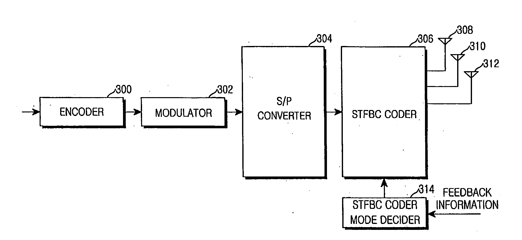
[0030] The above object is achieved by providing a transmitter for maximizing coding gain by transmitting an input symbol sequence through a plurality of transmit antennas according to feedback CQIs from a receiver in a 3 Tx-rate 2 communication system.

Problems solved by technology

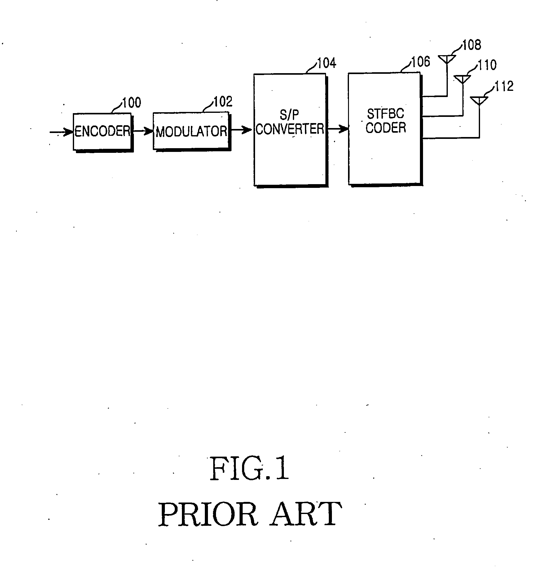
The distinctive drawback of the above-described conventional coding scheme is that diversity is achieved for the Alamouti-coded symbols s1, s2, s3, s4 but not for the non-Alamouti-coded symbols s5, s6, s7, s8 and thus s5, s6, s7, s8 are hard to recover and have a higher error probability, as compared to s1, s2, s3, s4.

Method used


Image

  • Apparatus and method for space-time-frequency block coding
  • Apparatus and method for space-time-frequency block coding
  • Apparatus and method for space-time-frequency block coding

Examples


Embodiment Construction

[0038] A preferred embodiment of the present invention will be described herein below with reference to the accompanying drawings. In the following description, well-known functions or constructions are not described in detail since they would obscure the invention in unnecessary detail.

[0039] The present invention is intended to provide an STFBC coding apparatus in a transmitter of a Tx-rate 2 communication system, more specifically a method and apparatus for generating an STFBC in the manner that maximizes the coding gain of the STFBC in a transmission scheme where an input symbol sequence is transmitted through a plurality of Tx antennas.

[0040] While the present invention is described in the context of an STFBC coding apparatus, it is also applicable to an STBC coding apparatus or an SFBC coding apparatus.

[0041]FIG. 3 is a block diagram of a transmitter in a mobile communication system using an STFBC scheme according to the present invention. The transmitter, similar to that i...


PUM


Abstract

A transmitter for maximizing coding gain by transmitting an input symbol sequence through a plurality of transmit antennas method according to feedback CQIs from a receiver in a 3 Tx-rate 2 communication system. In the transmitter, an S / P converter converts serial modulated data to parallel modulated data. A coder mode decider determines a transmission mode based on the channel quality indicator of each transmit antenna fed back from a receiver. A coder transmits the parallel modulated data through the three transmit antennas according to the determined transmission mode.

Description

PRIORITY [0001] This application claims priority under 35 U.S.C. § 119 to an application entitled “Apparatus And Method For Space-Time-Frequency Block Coding” filed in the Korean Intellectual Property Office on Nov. 4, 2004 and assigned Serial No. 2004-89507, the contents of which are herein incorporated by reference. BACKGROUND OF THE INVENTION [0002] 1. Field of the Invention [0003] The present invention relates generally to a transmitter in a communication system supporting a data rate of 2 for three transmit antennas (a 3 Tx-rate 2 communication system), and in particular, to a transmitter for maximizing a coding gain by transmitting an input symbol sequence through a plurality of transmit antennas according to feedback Channel Quality Indicators (CQIs) from a receiver in a 3 Tx-rate 2 communication system. [0004] Specifically, the present invention relates to a transmitter for space-time-frequency block coding (space-time block coding or space-frequency block coding) a transmis...

Claims


Application Information

Patent Timeline
IPC IPC(8): H04B7/06H04J99/00
CPCH04L1/0001H04L1/0009H04L1/0026H04L1/0606H04L1/0643H04L27/26
Inventor JEONG, HONG-SILCHAE, CHAN-BYOUNGYUN, SUNG-RYULROH, WON-ILOH, JEONG-TAEKO, KYUN-BYOUNGJUNG, YOUNG-HONAM, SEUNG-HOONCHUNG, JAE-HAK
Owner SAMSUNG ELECTRONICS CO LTD
Learn More