
Handheld vacuum with accelerated cyclonic flow and air freshener

a technology of cyclonic flow and vacuum, which is applied in the field of vacuums, can solve problems such as affecting its effectiveness, and achieve the effects of preventing the cyclonic flow from accelerating, and improving the efficiency of the centrifugal chamber

Inactive Publication Date: 2006-05-04
LAU YING WAI
View PDF3 Cites 230 Cited by
  • Summary
  • Abstract
  • Description
  • Claims
  • Application Information

AI Technical Summary

Benefits of technology

[0009] It is another object of the invention to provide a hand held vacuum with a centrifugal debris separation chamber that remains efficient when the centrifugal debris separation chamber is displaced from a vertical orientation.
[0010] It is still another object of the invention to provide a hand held vacuum with a centrifugal debris separation chamber that remains efficient when the centrifugal debris separation chamber undergoes a substantial amount of movement.
[0013] A hand held vacuum having a centrifugal chamber that serves as its primary filter is disclosed. The centrifugal chamber is tapered from its base to its distal end. The tapering will cause the air stream within the centrifugal chamber to accelerate as it moves toward the distal end. Debris entrained within the air steam will be less likely to fall out of the air stream at the higher speeds, thereby improving the efficiency of the centrifugal chamber as the vacuum is moved into various non-vertical positions.
[0014] The centrifugal chamber preferably has an outflow aperture that is proximate to its base and most preferably coextensive with the base. The tapered design of the centrifugal chamber will cause the air speed within the centrifugal chamber to increase as the air moves in the direction of the distal end of the centrifugal chamber. This will keep more of the debris in the air stream in the vicinity of the distal end of the centrifugal chamber and away from its outflow aperture, which will also improve the efficiency of the centrifugal chamber.
[0015] In the preferred embodiment, the vacuum is also provided with a filter housing. The filter housing contains a filter and is positioned so that air leaving the centrifugal chamber must pass through the filter housing. The filter acts as a secondary filter, preventing any dust and small debris that may escape from the cyclonic air stream from actually escaping from the centrifugal chamber itself.
[0016] The preferred embodiment also contains an air freshener in the filter housing. The air freshener will sublimate into the passing air stream and be emitted with the exhaust from the vacuum and / or any odor causing particles that may be in the air stream will be absorbed by the air freshener. The filter in the filter housing will prevent any dust and debris that may be in the airstream from adhering to the air freshener and thereby impeding its effectiveness.

Problems solved by technology

The filter in the filter housing will prevent any dust and debris that may be in the airstream from adhering to the air freshener and thereby impeding its effectiveness.

Method used


Image

  • Handheld vacuum with accelerated cyclonic flow and air freshener
  • Handheld vacuum with accelerated cyclonic flow and air freshener
  • Handheld vacuum with accelerated cyclonic flow and air freshener

Examples


Embodiment Construction

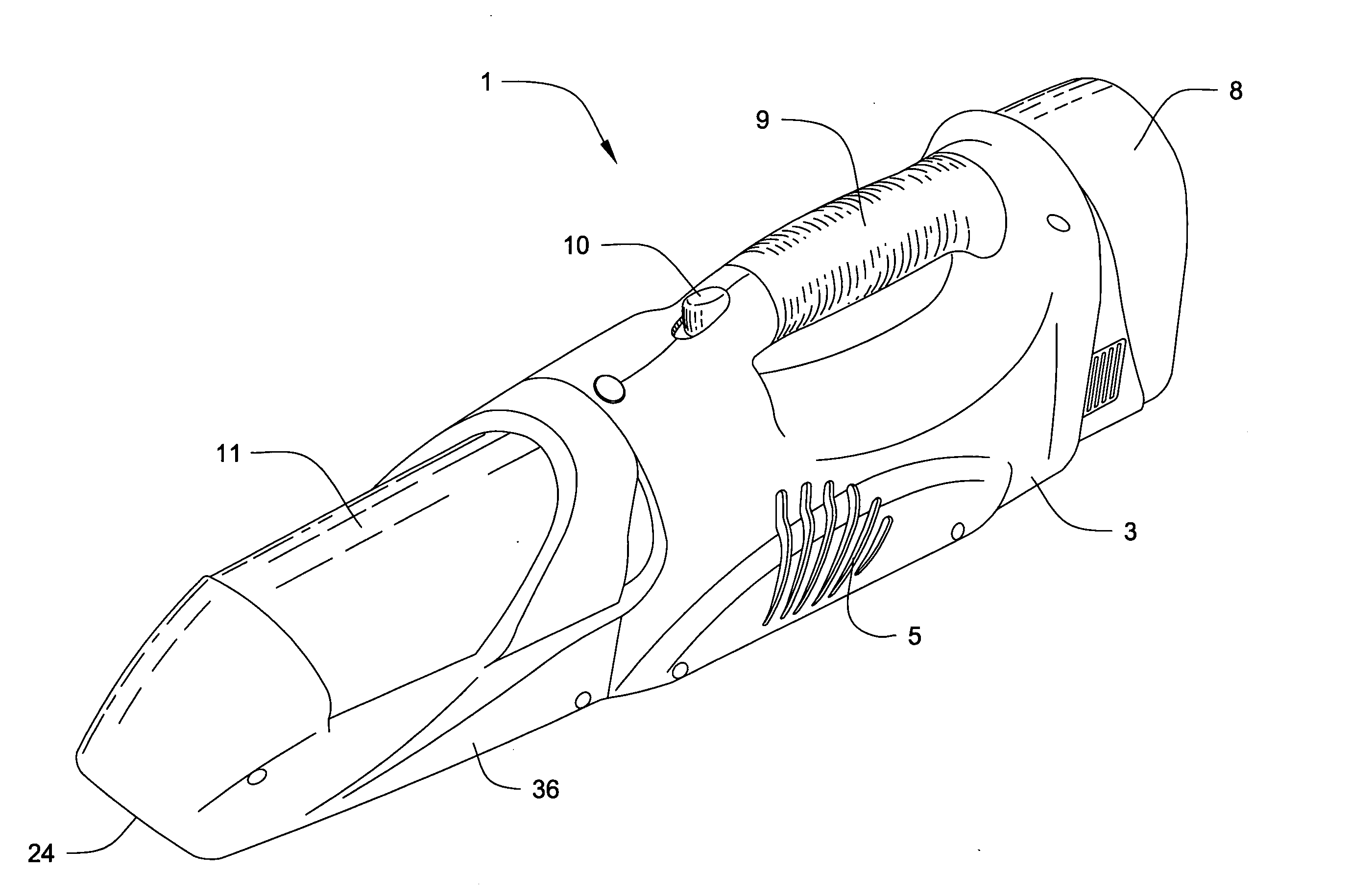
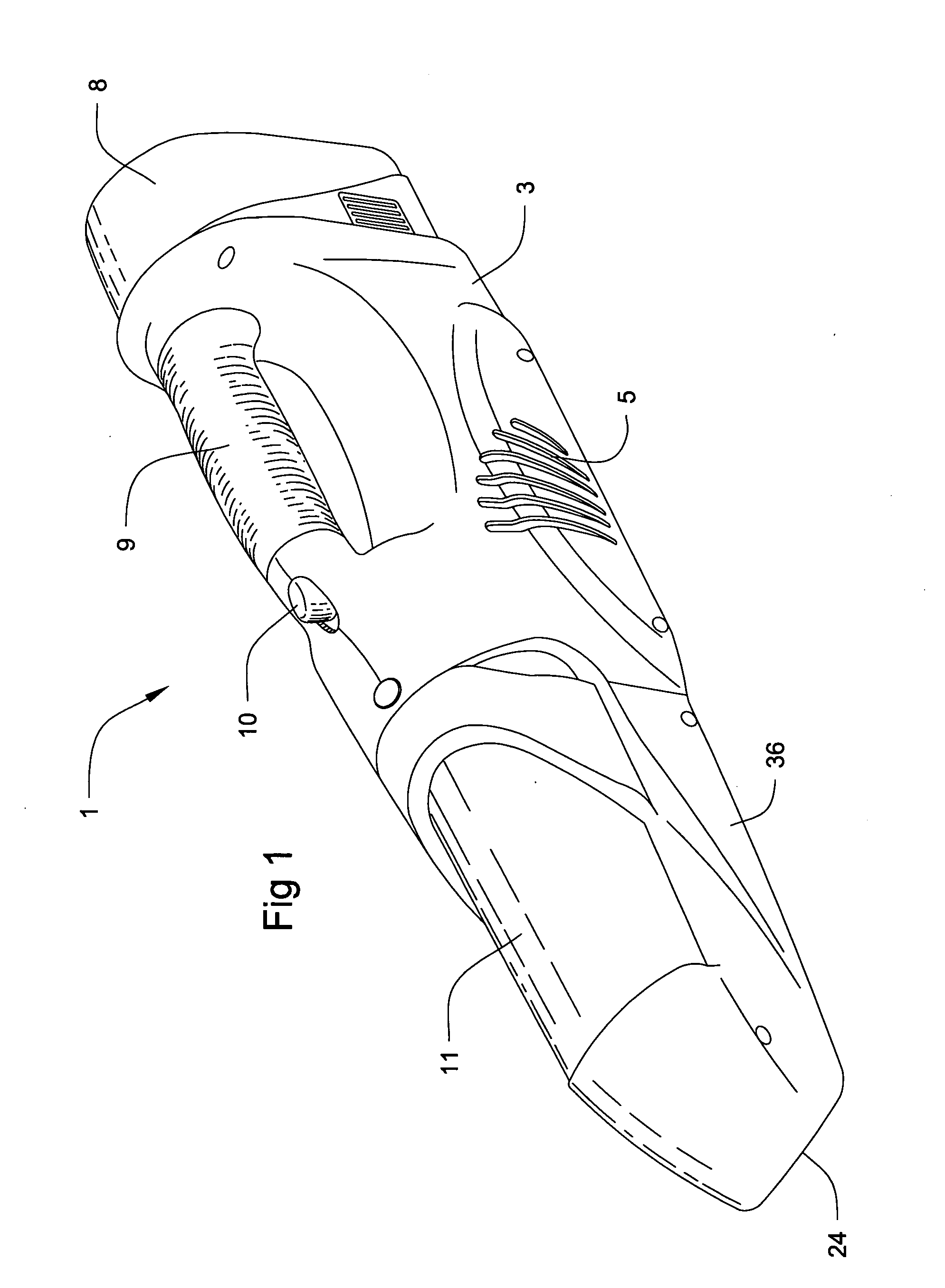
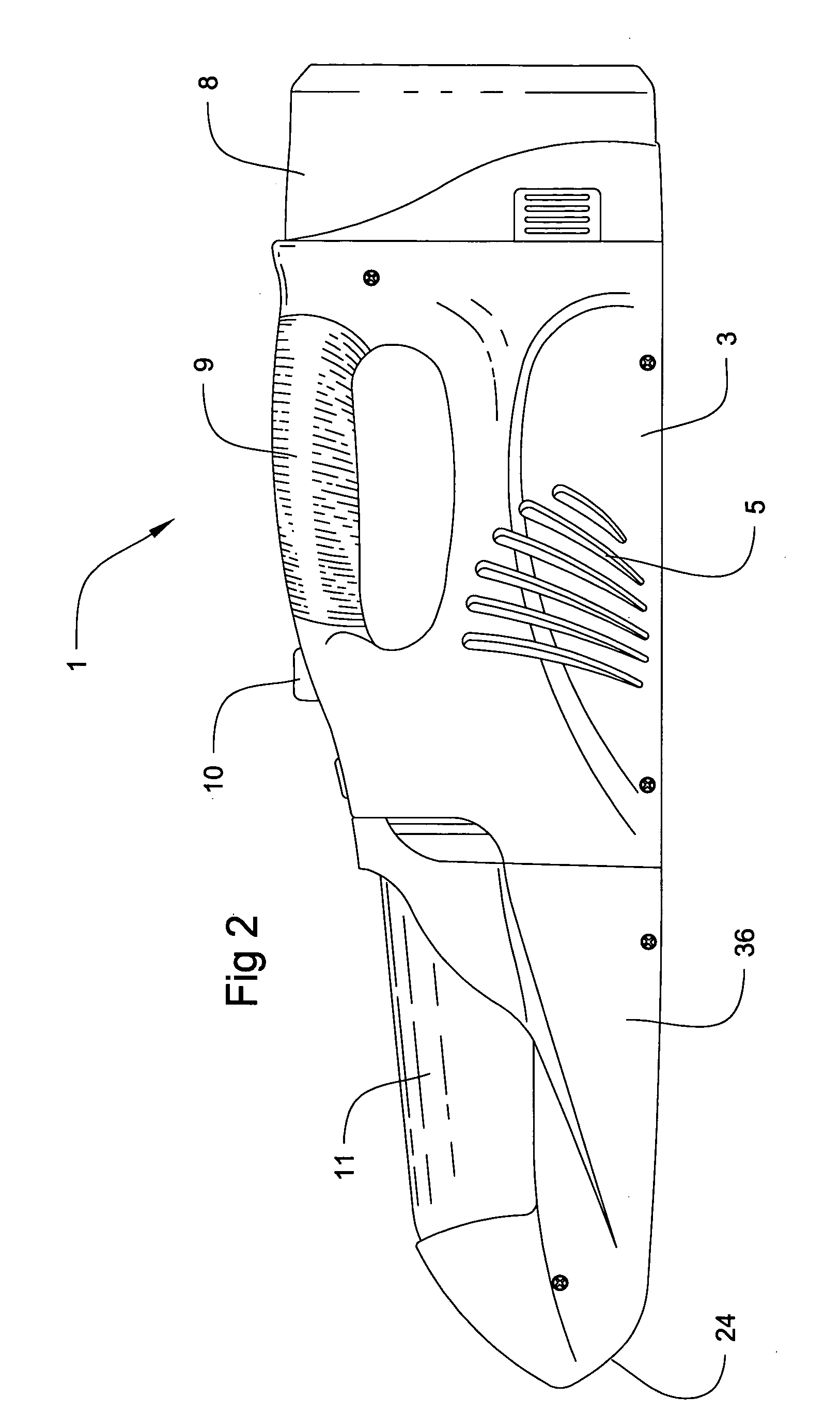
[0026] The invention is primarily directed toward hand held vacuums 1, that is vacuums 1 of less than about three feet in length and less than about one foot in either width or height. In the preferred embodiment, vacuum 1 includes a suction chamber 2. Suction chamber 2 comprises a suction housing 3 which will preferably include at least one intake aperture 4 and at least one outflow vent 5. Suction housing 3 will preferably include at least one motor 6. Motor 6 is configured to drive at least one fan 7 when motor 6 is activated. Fan 7 is positioned and configured to draw air into intake aperture 4, through suction housing 3 and out vent 5 when fan 7 is rotated. A power source 8 is provided in or on suction housing 3. Power source 8 may be a battery or batteries, an electrical line leading to a wall or automotive outlet, or any other conventional source of power suitable for operation of motor 6. Suction housing 3 will also preferably include a handle 9 and a switch 10 for activatin...


PUM


Abstract

A hand held vacuum having a tapered centrifugal chamber as its primary filter. The tapering causes the air stream within the centrifugal chamber to accelerate as it moves toward the distal end. The air steam will be able to retain more debris at higher speeds, thereby improving the efficiency of the centrifugal chamber. This will also keep more of the debris in the vicinity of the distal end of the centrifugal chamber and away from its outflow aperture. An air freshener in a filter housing is also provided. The air freshener will sublimate into the passing air stream and be emitted with the exhaust from the vacuum and / or any odor causing particles that may be in the air stream will be absorbed by the air freshener. The filter will prevent any dust and debris in the airstream from adhering to the air freshener and impeding its effectiveness.

Description

BACKGROUND OF THE INVENTION [0001] 1. Field of the Invention [0002] The invention relates to vacuums in general and hand held vacuums in particular. [0003] 2. Prior Art [0004] Cyclonic vacuums are known in the art. See, e.g., U.S. Pat. No. 4,373,228. In cyclonic vacuums, an air stream enters a cyclonic chamber and rotates as in a vortex. Essentially, centrifugal force drives the debris particles in the air stream to the outside of the vortex. The outlet from the cyclonic chamber is located near the center of the vortex. Thus, the motion of the air pushes the particles in the vortex to the outside, while relatively clean air exits the cyclonic chamber from a central location. However, most applications of this technology are used with upright vacuums. [0005] Problems arise when cyclonic chambers are moved out of a vertical orientation. To appreciate this, it is important to consider the path taken by the air stream within the cyclonic chamber. There are generally two paths of motion:...

Claims


Application Information

Patent Timeline
IPC IPC(8): A47L5/24
CPCA47L5/24A47L7/04A47L9/165
Inventor LAU, YING WAI
Owner LAU YING WAI
Learn More