Sensors for dynamically detecting substrate breakage and misalignment of a moving substrate

a sensor and substrate technology, applied in the field of apparatus and methods for detecting substrate breakage and misalignment of moving substrates, can solve the problems of collision not only chipping or cracking the flat-panel display substrate, but also increasing the positional accuracy of substrates throughout the processing system,

Active Publication Date: 2006-04-27
APPLIED MATERIALS INC
View PDF33 Cites 22 Cited by
  • Summary
  • Abstract
  • Description
  • Claims
  • Application Information

AI Technical Summary

Problems solved by technology

Increasing the positional accuracy of substrates throughout the processing system is a challenge.
It is difficult to ensure that flat-panel display substrates align properly with the end effectors of the robots, and once aligned, that the substrate can pass through slots or other obstacles in the load lock or process chambers without collisions due to a shift in alignment (i.e., misalignment) during transfer.
A collision may not only chip or crack the flat-panel display substrate, but also create and deposit debris in the load lock or process chambers.
Creating such debris may result in processing defects or other damage to the display or subsequently processed displays.
Thus, the presence of debris often requires shutting down the system, or a portion thereof, to thoroughly remove the potentially contaminating debris.
Accordingly, damage to the substrate or yield loss because of substrate misalignment is highly undesirable due to consequential increase in cost and reduction in throughput.
Although conventional sensor arrangements perform satisfactorily, in operation there are several inherent limitations associated with providing these arrangements of sensors.
Thus the transfer chamber robot is effectively limited to a single-arm robot which results in reduced throughput of the processing system.
Another limitation, which also contributes to a reduced throughput of the processing system, is that the substrate is stationary when positioned over the four sensors during the sensing of its alignment.
Still another limitation is at least four sensors are required to sense the alignment of a single substrate.
Finally, another limitation is that the four sensors detect substrate defects (e.g., a substrate chip) only at the corners of the substrate.

Method used


Image

  • Sensors for dynamically detecting substrate breakage and misalignment of a moving substrate
  • Sensors for dynamically detecting substrate breakage and misalignment of a moving substrate
  • Sensors for dynamically detecting substrate breakage and misalignment of a moving substrate

Examples


examples

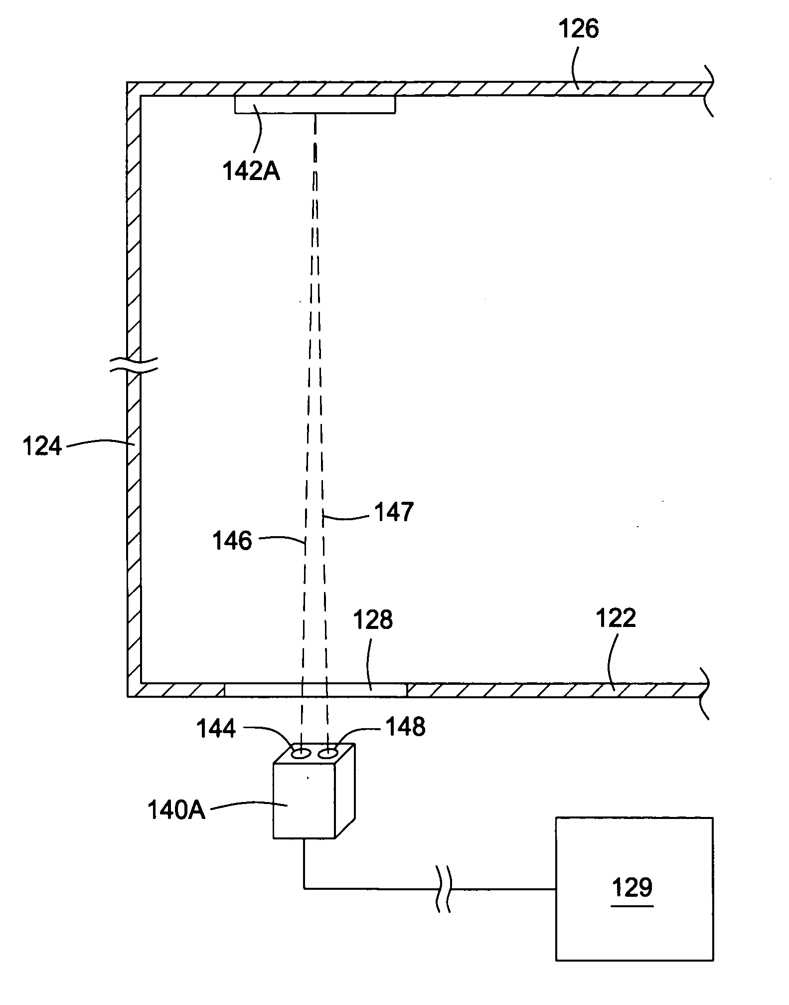
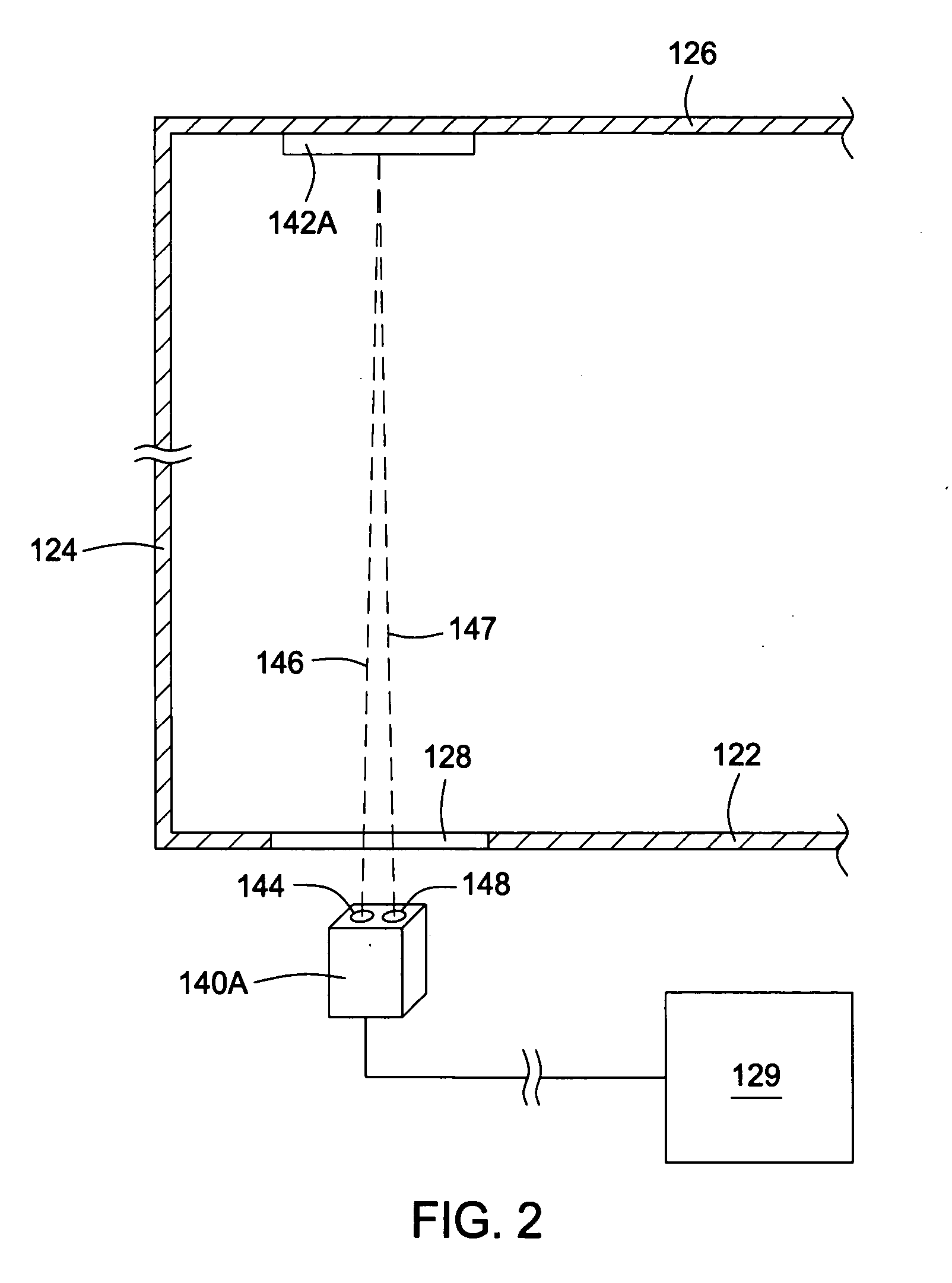
[0040] In one example, two Omron® Model No. E3C-LR11 laser sensors having a beam diameter of less than about 0.8 mm at working distances up to about 1000 mm (i.e., working distances of less than about 40 inches) is used to sense a substrate along its two parallel edges as the substrate, supported on an end effector of a dual-arm robot, passes the sensors. At a substrate transfer speed of about 1000 mm / s, defects having a size of about 3 mm or greater were detectable. The center of the impinging beam from each sensor was positioned at a distance of about 3 mm inward from the edges of the substrate. At a substrate transfer speed of about 100 mm / s, defects having a size of about 1 mm or greater were detectable, and at a substrate transfer speed of about 2000 mm / s, defects having a size of about 10 mm or greater were detectable. Thus, the two impinging beams for sensing a substrate being transferred at a speed in a range of about 100 mm / s to about 2000 mm / s are preferably positioned at ...


PUM

PropertyMeasurementUnit
diameteraaaaaaaaaa
diameteraaaaaaaaaa
velocityaaaaaaaaaa

Abstract

An apparatus and method incorporating at least two sensors that detect the presence of substrate defects, such as breakage or misalignment, along the lengths of at least two parallel edges of a moving substrate. In one embodiment, an apparatus for detecting substrate defects includes a sensor arrangement including at least two sensors that continuously sense a substrate near at least two parallel edges of the substrate as the substrate passes the sensors. In another embodiment, an apparatus for detecting substrate defects includes a robot having a substrate support surface, and a sensor arrangement including at least two sensors that continuously sense a substrate near at least two parallel edges of the substrate during substrate transfer on the substrate support surface. In another embodiment, a method of continuously detecting substrate defects includes positioning at least two sensors to continuously sense a substrate near at least two parallel edges of the substrate as the substrate passes the sensors, and transmitting a signal from each of the at least two sensors to a controller that continuously monitors the signals from the at least two sensors to detect the presence of a substrate defect.

Description

BACKGROUND OF THE INVENTION [0001] 1. Field of the Invention [0002] Embodiments of the present invention generally relate to an apparatus and method for detecting substrate breakage and misalignment of a moving substrate in a continuous and cost-effective manner. [0003] 2. Description of the Related Art [0004] Substrate processing systems are used to process substrates such as silicon wafers in the production of integrated circuit devices and glass panels in the manufacture of flat panel displays. Typically, one or more robots are disposed in the substrate processing system to transfer substrates through a plurality of process chambers for conducting a sequence of processing steps of the fabrication process. Generally, a substrate processing system includes a cluster tool having a centrally located transfer chamber, with a transfer chamber robot disposed therein, and a plurality of process chambers surrounding the transfer chamber. The transfer chamber is sometimes coupled to a fact...

Claims


Application Information

Patent Timeline
Patent Type & Authority Applications(United States)
IPC IPC(8): G01N21/88
CPCG01N21/9501H01L21/67265
Inventor BAGLEY, WILLIAM A.LEE, PAOHUEIKIM, KYUNG-TAEKIM, SAM-KYUNGKIYOTAKE, TOSHIOKIM, SAMMATSUMOTO, TAKAYUKILARSON, JONATHAN ERIKINAGAWA, MAKOTOHOFFMAN, JAMESLEUNG, BILLY C.
Owner APPLIED MATERIALS INC
Why Eureka
Try Eureka