
Swing door opening/closing detection system

a detection system and door technology, applied in the direction of motor/generator/converter stopper, dynamo-electric converter control, instruments, etc., can solve the problem of door main body malfunction, and achieve the effect of reducing the number of parts and saving spa

Inactive Publication Date: 2006-04-27
OPTEX CO LTD
View PDF3 Cites 11 Cited by
  • Summary
  • Abstract
  • Description
  • Claims
  • Application Information

AI Technical Summary

Benefits of technology

[0008] Therefore, considering the above-described circumstances, it is an object of the present invention to provide a swing door opening / closing detection system that is capable of preventing a malfunction of door main bodies by accurately discriminating an opening / closing position of the door main bodies and controlling the rotary driving of the door main bodies based on the discrimination result.
[0011] Here, when the door main body is rotary driven, the deformation part deforms according to the rotational operation of the door main body. Then, the discriminating part discriminates the opening / closing position of the door main body based on the deformation amount of the deformation part, to thereby control the control part based on the discrimination result. This configuration enables accurate discrimination (recognition) of the opening / closing position of the door main body, and the control part can accurately control the driving part and the door main body based on the discrimination result. Therefore, the malfunction of the door main body can be prevented.
[0014] In an embodiment, since the deformation part is the wiring cover protecting the electrical wiring connected to the sensing part, the wiring cover indispensable for the electrical wiring can be used for discriminating the opening / closing position of the door main body. This can reduce not only the number of parts but also manufacturing cost, compared with a case where a separate member is used for discriminating the opening / closing position of the door main body.
[0016] According to another aspect of the invention, since one end of the wiring cover is attached to the door main body to be rotatable about the axis and the other end of the wiring cover is fixed to the fixed wall, the wiring cover torsionally deforms according to the rotational operation of the door main body when the door main body is rotary driven. Then, the discriminating part discriminates the opening / closing position of the door main body based on the torsional deformation amount of the wiring cover to control the control part based on the discrimination result. This enables accurate discrimination (recognition) of the opening / closing position of the door main body, and the control part can accurately control the driving part and the door main body based on the discrimination result. Therefore, the malfunction of the door main body can be prevented.
[0018] According to a further aspect of the invention, the deformation part is one of the electrical wiring connected to the sensing part and the bending deformation member included in the electrical wiring, and the discriminating part discriminates the opening / closing position of the door main body based on the bending deformation amount of one of the electrical wiring and the bending deformation member that bendingly deform in accordance with the rotational operation of the door main body, and controls the control part based on the discrimination result. This enables accurate discrimination (recognition) of the opening / closing position of the door main body, and the control part can accurately control the driving part and the door main body based on the discrimination result. Therefore, the malfunction of the door main body can be prevented.
[0020] According to an aspect of the invention where the sensing part also functions as the discriminating part, it is possible to reduce the number of parts and the trouble accompanying the installation. Further, less installation space is required compared with a case where a separate member serves as the sensing part and the both units are provided in a space near the swing door, so that space saving is achieved.

Problems solved by technology

Therefore, controlling the rotary driving of the door main bodies based on information from the object sensors involves a possibility of causing a malfunction of the door main bodies.

Method used


Image

  • Swing door opening/closing detection system
  • Swing door opening/closing detection system
  • Swing door opening/closing detection system

Examples


Embodiment Construction

[0028] Next, a swing door opening / closing detection system according to one embodiment of the present invention will be described with reference to the drawings.

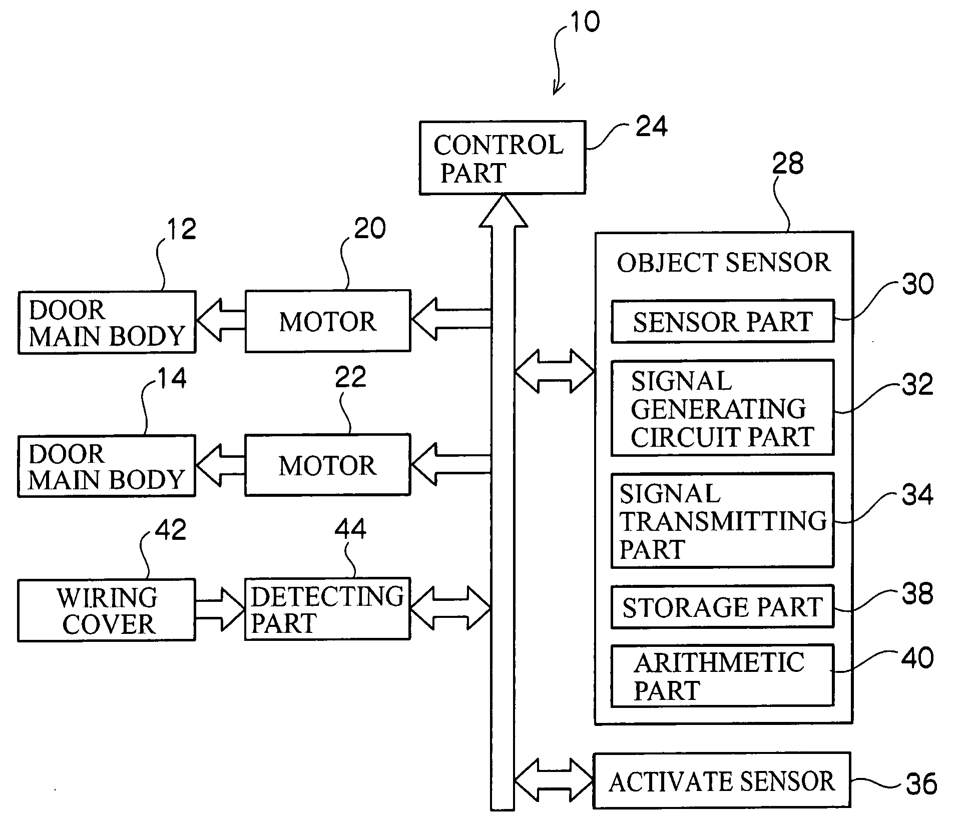
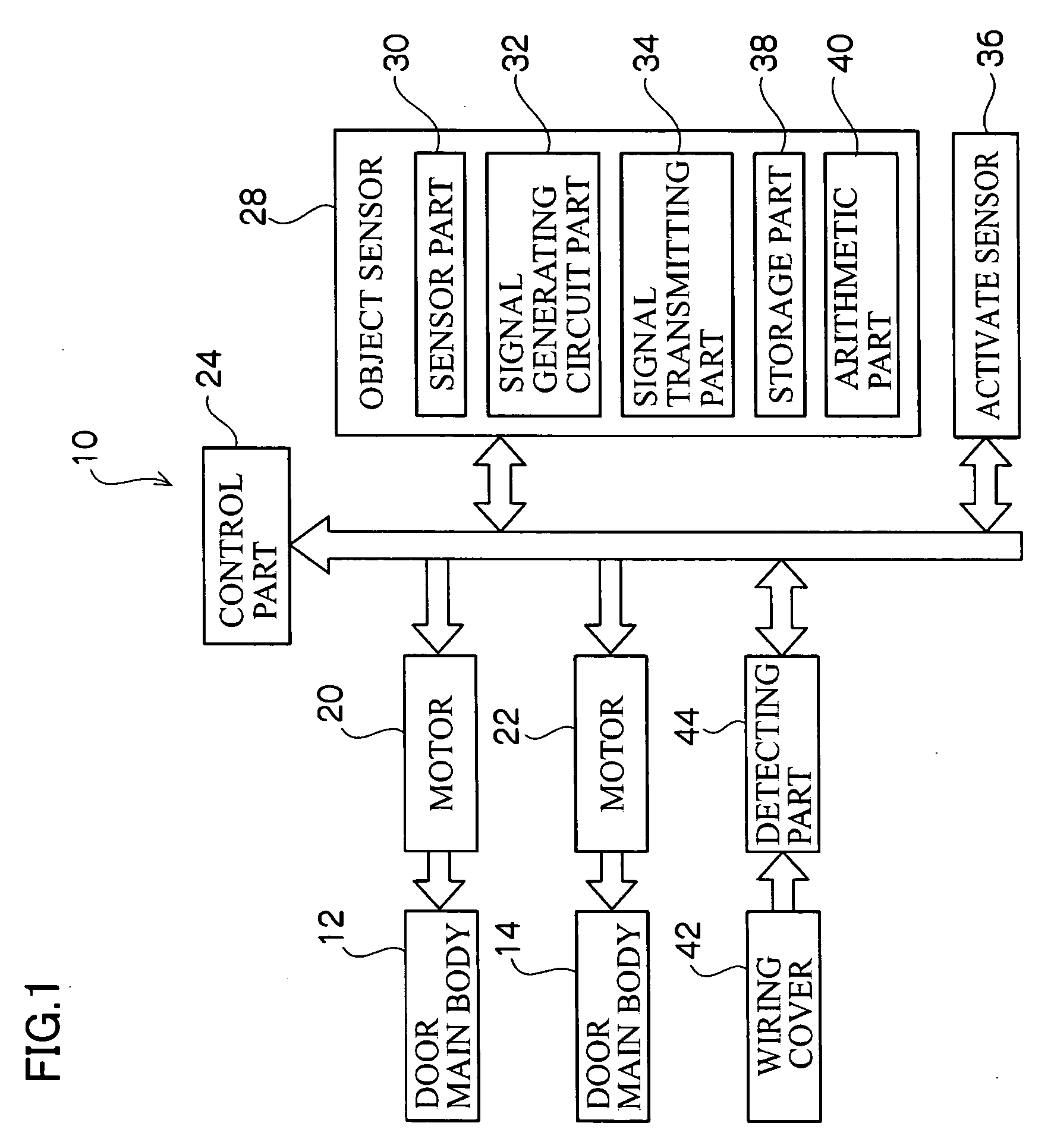
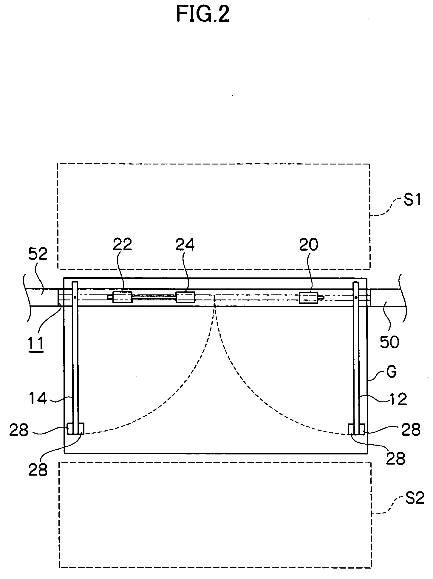
[0029] As shown in FIG. 1 to FIG. 3, a swing door opening / closing detection system 10 includes a swing door. The swing door is composed of a pair of door main bodies 12, 14. The door main bodies 12, 14 are formed in a rectangular shape, and on outer widthwise end portions of the door main bodies 12, 14, hinges 56 (hinge on one side is not shown) are attached to span onto fixed walls 50, 52 respectively. Thus, the door main bodies 12, 14 are rotatably attached to the fixed walls 50, 52 via the hinges 56. Further, motors (driving parts) 20, 22 for rotary driving the door main bodies 12, 14 are disposed near the opening part 11, and when the motors 20, 22 are driven, the door main bodies 12, 14 are rotary driven. A control part (control part) 24 for controlling the driving of the motors 20, 22 is further disposed near the moto...


PUM


Abstract

The present invention provides a swing door opening / closing detection system capable of accurately discriminating an opening / closing position of door main bodies to accordingly prevent the malfunction of the door main bodies. The swing door opening / closing detection system includes: door main bodies 12, 14 which are rotatably provided and which rotate to open / close relative to an opening part 11; driving parts 20, 22 rotary driving the door main bodies 12, 14; a control part 24 controlling the rotary driving of the door main bodies 12, 14 by the driving parts 20, 22; a sensing part 30 (28) attached to the door main bodies 12, 14 to sense a person or an object in sensing areas on paths of the door main bodies 12, 14; a deformation part 42 deforming according to the rotational operation of the door main bodies 12, 14; and a discriminating part 40 (28) which discriminates the opening / closing position of the door main bodies 12, 14 based on a deformation amount of the deformation part 42 to control the control part 24 based on the discrimination result.

Description

BACKGROUND OF THE INVENTION [0001] 1. Field of the Invention [0002] The present invention relates to a swing door opening / closing detection system capable of detecting the opening / closing position of a swing door. [0003] 2. Description of the Related Art [0004] Conventionally, a so-called double-leaf automatic swing door system has been known. As shown in FIG. 7, a double-leaf automatic swing door system 100 includes: a pair of door main bodies 102, 104 disposed in an opening part 101; motors 110, 112 rotating the respective door main bodies 102, 104 on rotary shafts 106, 108 attached to the respective door main bodies 102, 104; and a control part 114 controlling the motors 110, 112. The door main bodies 102, 104 in a closed position are positioned so that one-side widthwise end portions thereof face each other. Driving one or both of the door main bodies 102, 104 in this position by the motor(s) 110, 112 causes one or both of the door main bodies 102, 104 to rotate on the rotary sh...

Claims


Application Information

Patent Timeline
Patent Type & Authority Applications(United States)
IPC IPC(8): G05D3/00
CPCE05Y2400/326E05Y2400/54E05Y2400/654E05F15/73E05Y2800/40E05Y2900/132E05F15/43E05Y2600/46
Inventor MATSUYAMA, TOSHIYASUTAKADA, YASUHIRO
Owner OPTEX CO LTD
Learn More