
Power lift and tilt modules

a technology of power lift and module, which is applied in the direction of wheelchair/patient conveyance, movable seat, chair, etc., can solve the problems of premature wear of the actuator, high load on the actuator,

Inactive Publication Date: 2006-04-27
SUNRISE MEDICAL HHC INC
View PDF7 Cites 58 Cited by
  • Summary
  • Abstract
  • Description
  • Claims
  • Application Information

AI Technical Summary

Problems solved by technology

Such actuators encounter a high load from an initial or lowered position.
This high load typically causes premature wear of the actuator.

Method used


Image

  • Power lift and tilt modules
  • Power lift and tilt modules
  • Power lift and tilt modules

Examples


Embodiment Construction

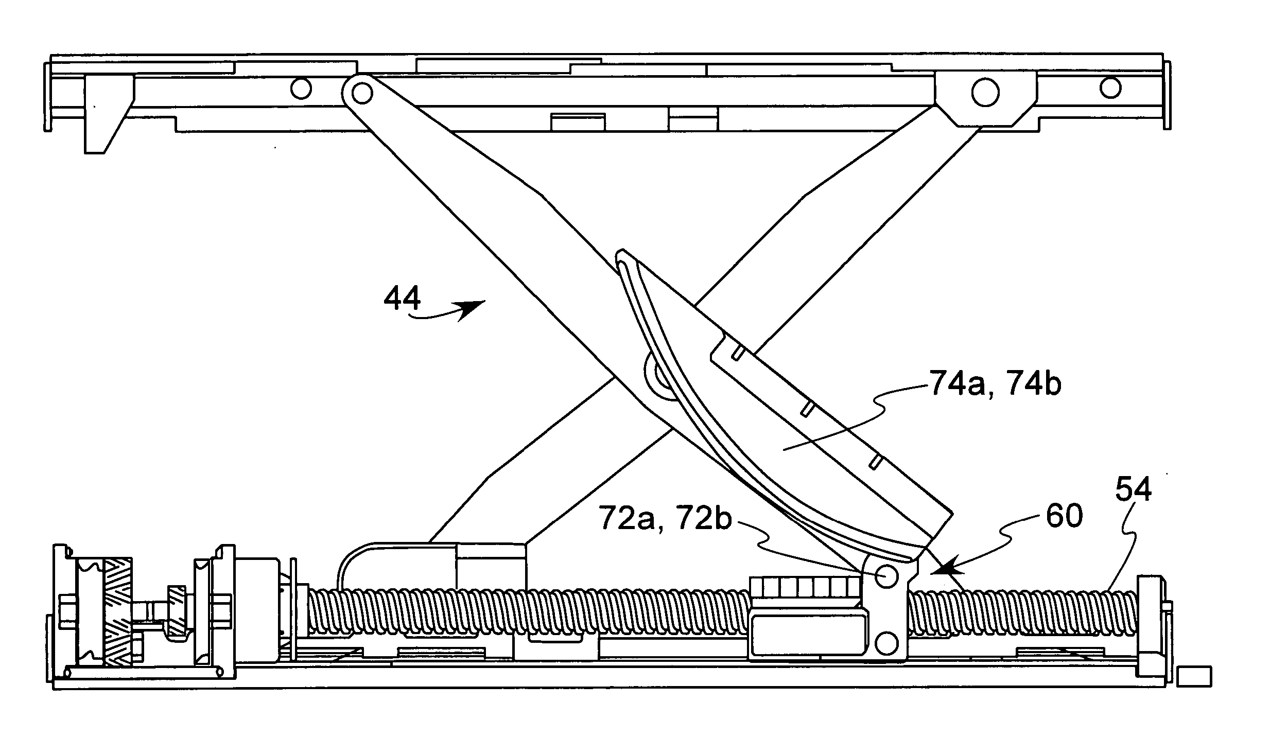
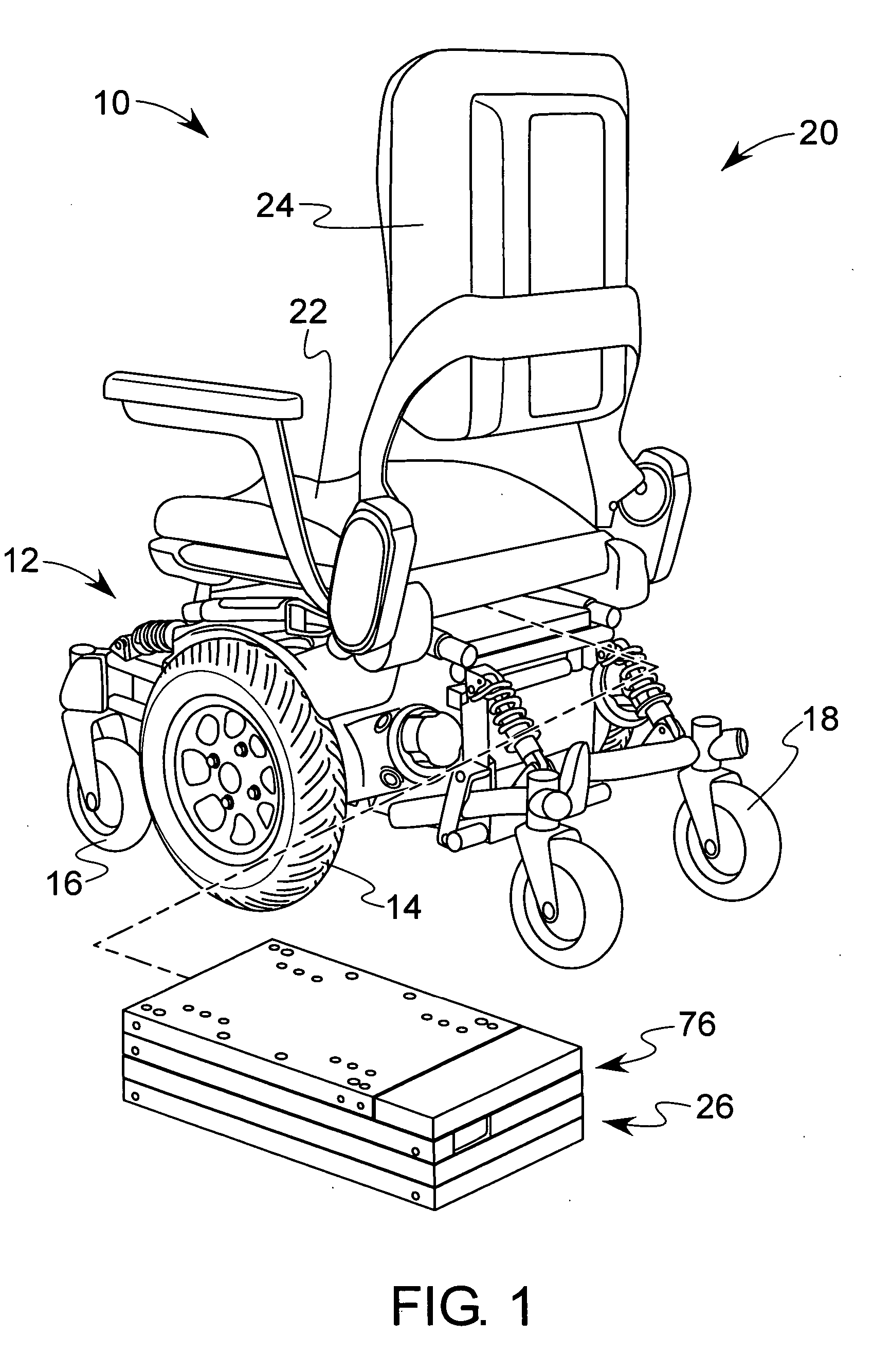
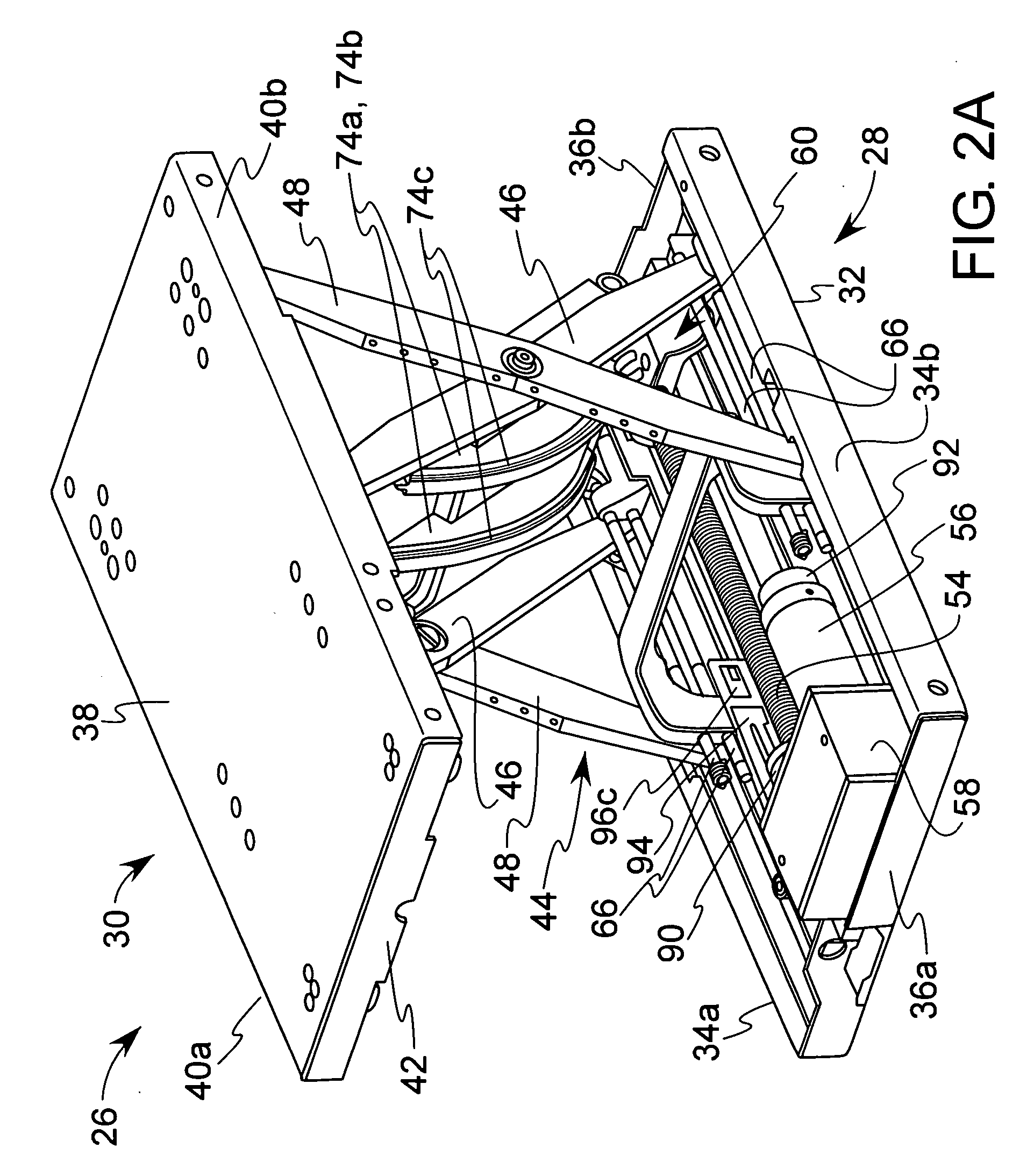
[0019] Referring now to the drawings, there is illustrated in FIG. 1 a wheelchair 10 and a modular actuator according to the present invention. The wheelchair 10 is a power wheelchair and more particularly, a mid-wheel drive wheelchair, although the invention can be practiced with other suitable drive configurations, such as front and rear wheel drive configurations. The wheelchair 10 comprises a base 12, which includes a frame supported on a supporting surface by a plurality of wheels, such as drive wheels 14, front wheels 16, and rear wheels 18, as shown in the drawing. The drive wheels 14 can be powered by any suitable power source and can be controlled by any suitable input device, including but not limited to a joystick (not shown). A seat assembly 20 is supported by the base 12. The seat assembly 20 comprises a seat 22 and a seat back 24, which may articulate (i.e., recline) relative to the seat 22. According to the present invention, the seat assembly 20 is adapted to be supp...


PUM


Abstract

A modular actuator has a combination cam member and scissors mechanism in a compact unit that is capable of lifting heavy loads. A pull member is capable of controlling and combining two different mechanisms that travel at different rates through two ranges of motion. The cam member has a profile that is dimensioned and configured to maintain a constant range of motion.

Description

CROSS REFERENCE TO RELATED APPLICATIONS [0001] This application claims the benefit of U.S. Provisional Patent Application No. 60 / 621,439, filed on Oct. 22, 2004.BACKGROUND OF INVENTION [0002] This invention relates in general to personal mobility vehicles and more particularly, to seating systems for personal mobility vehicles. Most particularly, this invention relates to the mechanisms for lifting and / or tilting seat assemblies for wheelchairs and like vehicles. [0003] Mechanisms for lifting and / or tilting wheelchair seat assemblies are well known. Such mechanisms typically include an actuator (i.e., a lead screw, nut, motor, and gearbox). By convention, parts of the actuator are integrated in the base and parts of the actuator are integrated in the seat assembly. Such actuators encounter a high load from an initial or lowered position. This high load typically causes premature wear of the actuator. A lifting and / or tilting mechanism is needed that is in the form of a compact unit ...

Claims


Application Information

Patent Timeline
IPC IPC(8): A47C1/06
CPCA61G5/043A61G5/1059A61G5/1075A61G2005/1089B66F7/0608B66F7/065A61G5/1089
Inventor TRIPPENSEE, DARIN J.DICKIE, PAUL C.STEVENS, REX W.LOCKTON, THOMASVAUGHT, JESSE A.LO, CHENG LENGLANGLEY, GREGORY A.
Owner SUNRISE MEDICAL HHC INC
Learn More