Automatic damper control for air conditioning system humidifier

a technology of automatic damper control and air conditioning system, which is applied in the direction of ventilation system, heating type, domestic cooling apparatus, etc., can solve the problems of homeowners or system operators often forgetting

Inactive Publication Date: 2006-04-27
TRANE INT INC
View PDF7 Cites 17 Cited by
  • Summary
  • Abstract
  • Description
  • Claims
  • Application Information

AI Technical Summary

Benefits of technology

[0003] The present invention provides an air conditioning system humidifier including an automatically controlled damper whereby, when flow of air through the humidifier is not required, it is automatically shut off by a movable closure member that substantially prevents airflow through the humidifier.
[0004] In accordance with one aspect of the present invention, a humidifier for an air conditioning system includes a damper operable to control airflow through the humidifier and which is responsive to a predetermined temperature in the system supply air to move from a closed position to an open position. For example, when the system supply air is being heated during operation of the system furnace or heating element, a sensor is operable to move the damper to an open position since humidification of the heated air will usually be required. One preferred embodiment of a sensor and damper actuator is provided wherein the damper comprises a closure member having a shaft part connected to a bimetallic sensor and actuator which, in response to a predetermined increase in supply air temperature, will move the damper closure member from a closed position to an open position. The sensor and actuator is preferably disposed in the supply air flowstream at a location downstream of the system furnace or heating element. When the supply air temperature is reduced below a predetermined value, the sensor and actuator will effect movement of the closure member back to the closed position.

Problems solved by technology

However, the homeowner or system operator often forgets to move the damper to the closed position during operation of the system in periods of ambient climate conditions wherein humidification of the system supply air is normally not required.

Method used


Image

  • Automatic damper control for air conditioning system humidifier
  • Automatic damper control for air conditioning system humidifier
  • Automatic damper control for air conditioning system humidifier

Examples


Embodiment Construction

[0014] In the description which follows like parts are marked throughout the specification and drawings with the same reference numerals, respectively. The drawing figures may not necessarily be to scale and certain elements and features may be shown in generalized or somewhat schematic form in the interest of clarity and conciseness.

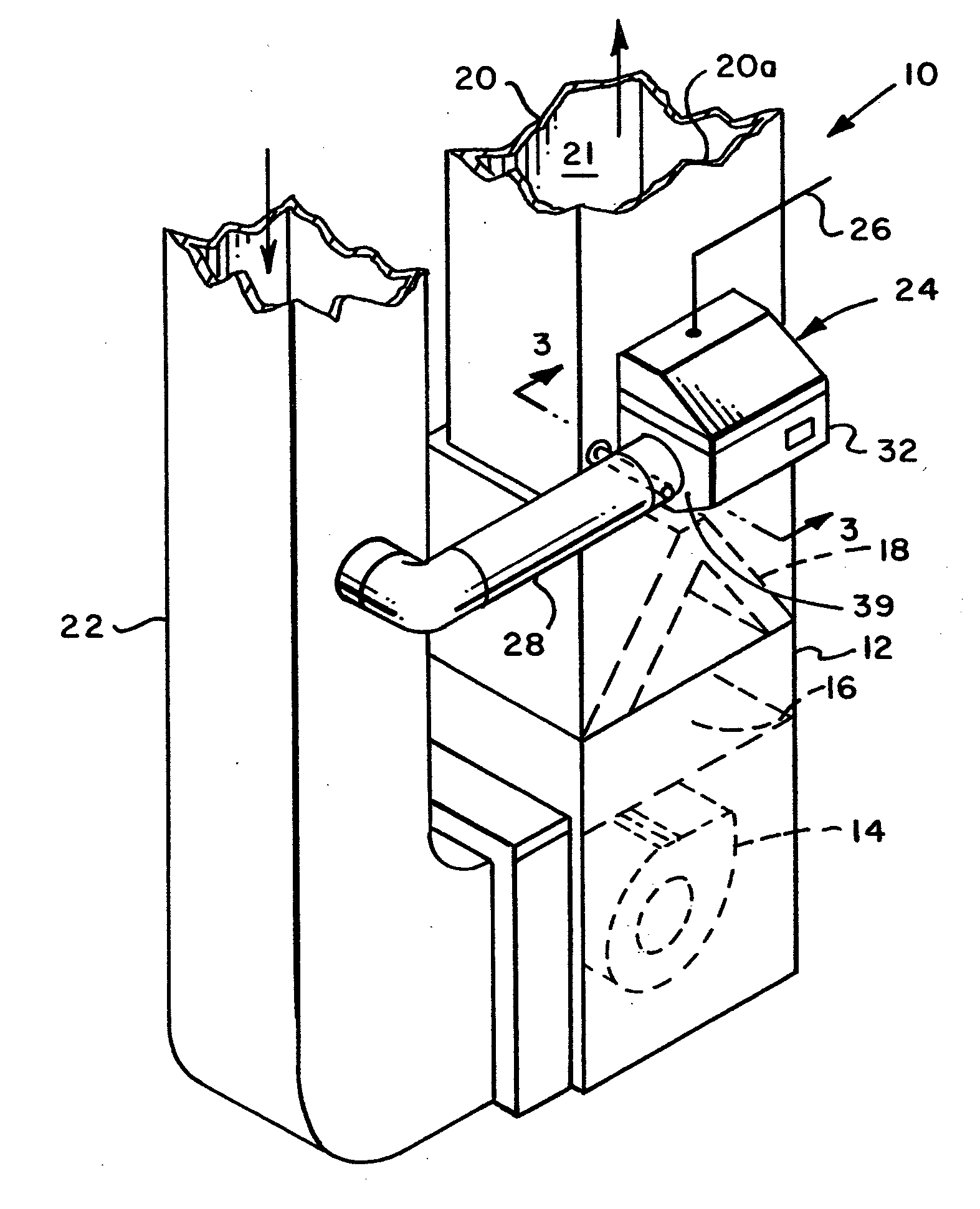
[0015] Referring to FIG. 1, there is illustrated a generally conventional forced air upflow air conditioning system 10 typical of forced air residential heating and cooling systems. The air conditioning system 10 is characterized by a generally rectangular hollow cabinet 12 in which is disposed a motor-driven fan or blower 14, above which may be disposed a heat exchanger 16, such as a gas furnace or an electric grid resistance heater. Also disposed in the cabinet 12 and generally above the heat exchanger 16 is a fin and tube type heating and / or cooling heat exchanger 18 of the so-called A-frame configuration and typically characterized as an evaporator...


PUM

PropertyMeasurementUnit
Temperatureaaaaaaaaaa
Flow rateaaaaaaaaaa
Humidityaaaaaaaaaa

Abstract

A forced airflow air conditioning system includes a humidifier which is operable to humidify air bypassed from a supply air plenum to a return air duct or vice versa, the humidifier airflow being controlled by a damper closure member which is operably connected to a bimetal spring actuator or to an electric motor, both responsive to temperature of air flowing through the system. One embodiment includes an electric motor connected to the damper closure member and in circuit with a humidistat for opening the damper when humidification is required.

Description

BACKGROUND OF THE INVENTION [0001] Conventional forced air residential and commercial air conditioning systems often include humidifiers for maintaining proper relative humidity in the system supply air, typically during the heating season in certain climates but also during year-round operation in certain other climates. One widely used type of humidifier is known as a bypass type which is typically configured such that the humidifier unit itself mounts on the system supply air plenum or cabinet, typically downstream of the furnace heat exchanger and the system cooling coil or evaporator. At least a portion of the conditioned air flowing through the plenum is bypassed through the humidifier and through a so-called bypass duct to the return air plenum upstream of the system cabinet. In this way, a suitable pressure differential is maintained by the system blower or fan to provide for air flow through the humidifier. [0002] During operation of the system wherein cooling of the supply...

Claims


Application Information

Patent Timeline
IPC IPC(8): F24F7/00F28D5/00B01F23/10
CPCF24F3/14F24F11/0012F24F11/0015F24F13/1426F24F2006/146F24F2013/1433F24F2013/146F24F11/30F24F2110/10F24F2110/20F24F11/76
Inventor HELT, ROBERT W.MUTCHNIK, KARL J.
Owner TRANE INT INC
Why Eureka
Try Eureka