Can opener

a can opener and operable technology, applied in the field of manual operation of can openers, can solve the problems of counterbalancing cutting head and drive knob, and achieve the effect of improving the handle or the grip

Inactive Publication Date: 2006-04-27
BRADSHAW INT
View PDF21 Cites 2 Cited by
  • Summary
  • Abstract
  • Description
  • Claims
  • Application Information

AI Technical Summary

Benefits of technology

[0004] The can opener of the present invention has an improved handle or grip that is disposed on top of the can during operation, to be held by one hand of the operator above the can, with a cutting head that is engageable with the can and has a drive knob on the cutting head that is operable by the other hand of the operator to turn the cutter in engagement with the can. The handle counterbalances the cutting head and drive knob so that the center of balance or center of gravity of the opener in the operating condition is over the top of the can. Accordingly, the opener rests in a stable manner on top of the can in the operating position and the user can interrupt the operation and simply leave the opener in place on the can.

Problems solved by technology

The handle counterbalances the cutting head and drive knob so that the center of balance or center of gravity of the opener in the operating condition is over the top of the can.

Method used


Image

  • Can opener
  • Can opener
  • Can opener

Examples


Embodiment Construction

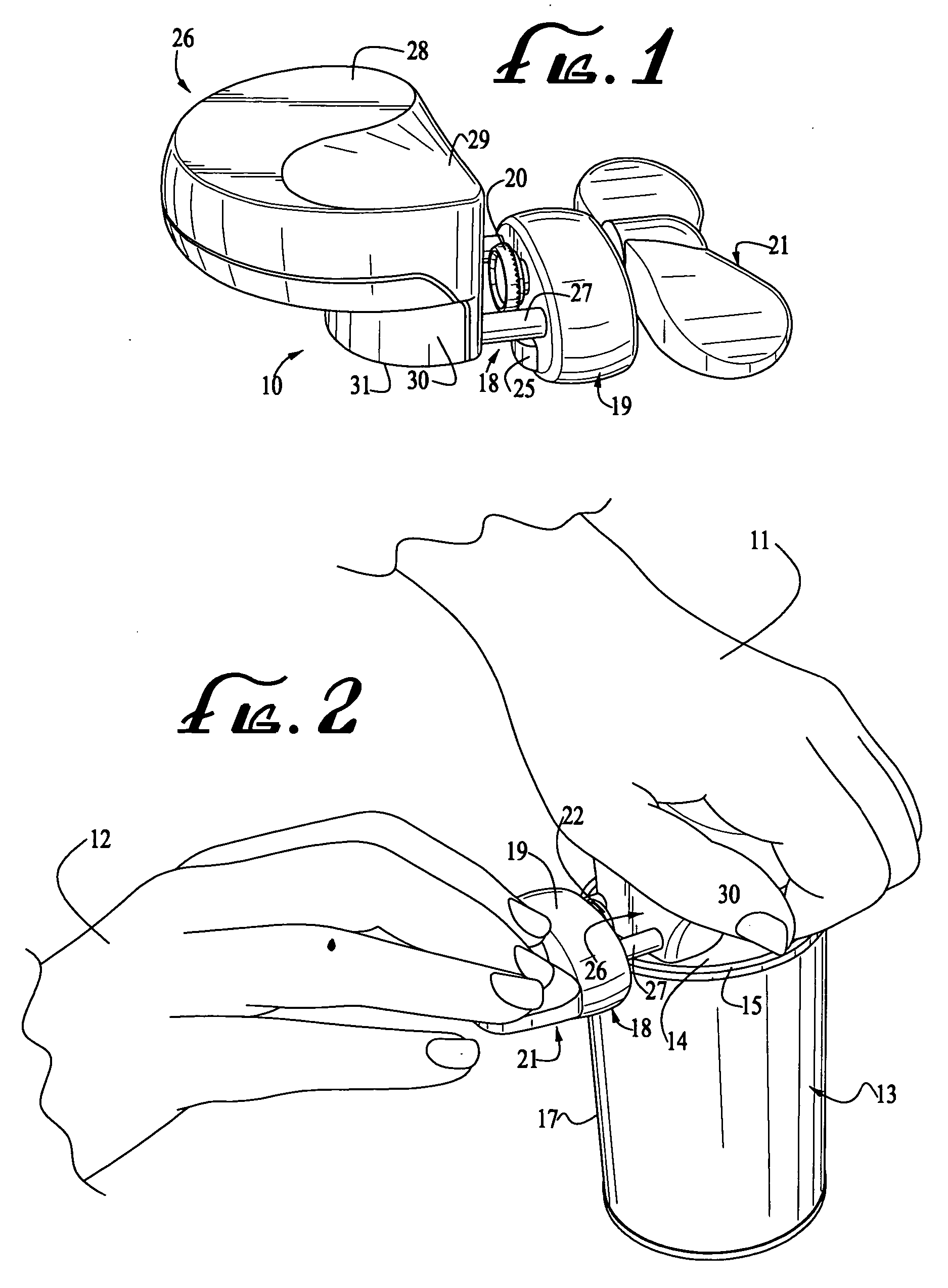
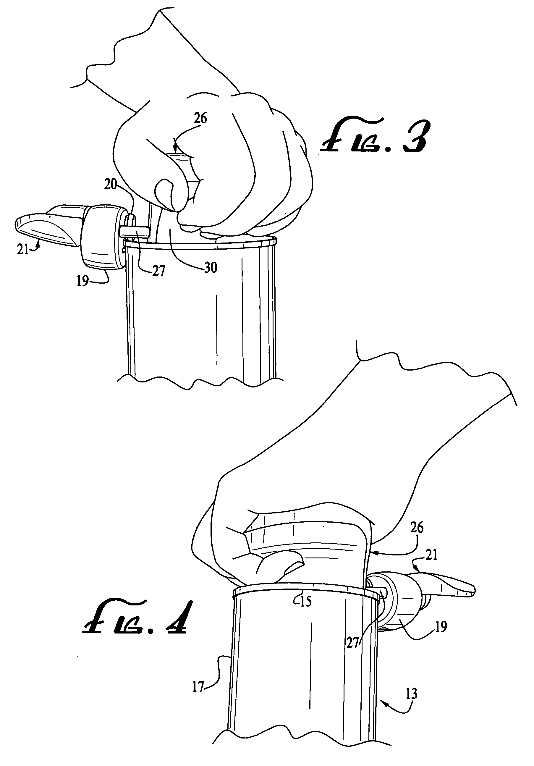
[0016] As shown in the drawings for purposes of illustration, the invention is embodied in a can opener 10 for use by a user, whose hands 11 and 12 are shown, to open cans such as the representative cylindrical can 13 shown in FIG. 2. This is accomplished by removing the top 14 from the can. Such cans typically have a rim 15 around the top that jams the top 14 to the body 17 of the can, and the can opener 10 cuts either the top or the sidewall along this rim to permit removal of the top.

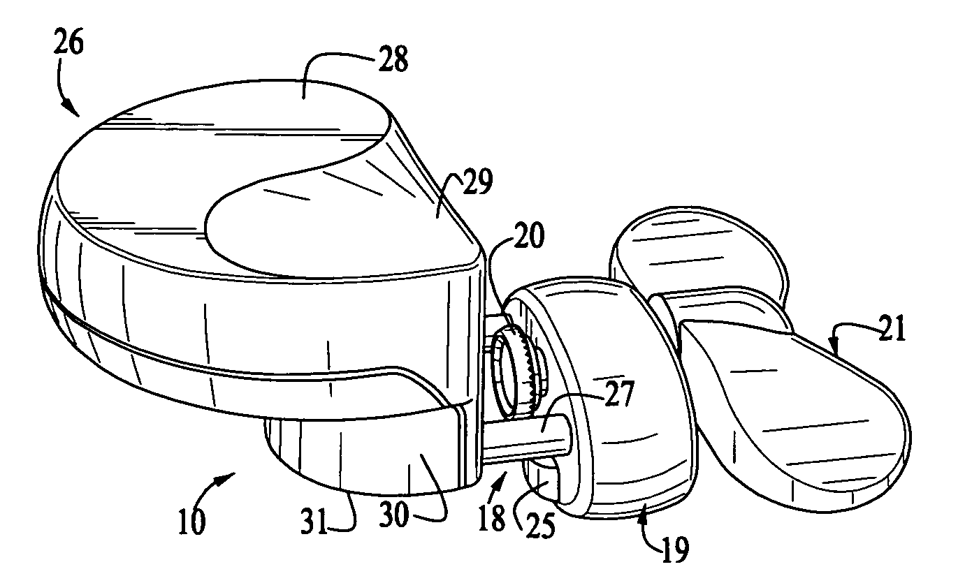
[0017] The can opener 10 has a cutting head, indicated generally at 18, that may be of basically conventional construction, including a block-shaped body 19 that can be positioned alongside the can 13 at the rim 15 and a rotary drive wheel 20 to be fitted over the can 13 and engaged with the inner side of the rim 15, as shown most clearly on FIGS. 3 and 8. A manually operable rotary drive knob 21, wherein a double-ended crank, and a cutter 22 are mounted on the body and the cutter is positioned to b...


PUM


Abstract

A can opener having a knob-shaped handle to be disposed over a can to be opened, a rotary cutting mechanism on a cutting head spaced from the handle, and a drive knob for the cutting mechanism on the side remote from the handle, the cutting head and drive knob being counterbalanced by the handle so that the center of gravity is over the can near the cutting mechanism. The handle has a flat, palm-engaging top surface, a beveled thumb-engaging surface along the upper edge near the cutting head, and a recessed side remote from the cutting head concavely tapering from the top surface to a flat lower side for engaging the top of the can near the cutting mechanism. The cutting head and drive knob are supported on the handle by parallel pins that bear on the rim of the can on opposite sides of the cutting mechanism.

Description

CROSS-REFERENCE TO RELATED APPLICATION [0001] This non-provisional application claims priority under 35 U.S.C. §119(e) on U.S. Provisional Application No. 60 / 602,652 filed on Aug. 19, 2004, the entire contents of which are hereby incorporated by reference.BACKGROUND OF THE INVENTION [0002] This invention relates to implements for removing the tops of cans, usually composed of metal, by cutting the top from the can. The invention relates more particularly to manually operable can openers that can be placed on the top of the can and having a cutting mechanism that is manually operated to travel around the typically curved top and open the can. [0003] Can openers of a wide variety of types have been known and used for many years to open cans and gain access to their contents. These range from quite simple tools with cutting blades that puncture and cut the top, to more complex openers that can be secured to the top of the can and include a hand actuator for turning of a rotary cutting ...

Claims


Application Information

Patent Timeline
Patent Type & Authority Applications(United States)
IPC IPC(8): B67B7/46
CPCB67B7/32
Inventor PARLOWSKI, JURGEN
Owner BRADSHAW INT
Why Eureka
Try Eureka