
Daytime stellar imager

Inactive Publication Date: 2006-04-20
TREX ENTERPRISES CORP
View PDF2 Cites 15 Cited by
  • Summary
  • Abstract
  • Description
  • Claims
  • Application Information

AI Technical Summary

Benefits of technology

[0012] Systems designed by Applicants include very efficient optical sensors, which increases the probability of detecting stars during daytime by several orders of magnitude, as compared with a prior art approach based on CCD cameras operating at visible wavelengths. The latter is due to several factors including:
[0016] Additional advantages of this design approach are associated with the fact that atmospheric obscurants including haze and smoke affect infrared sensors less than sensors operating in the visible waveband, and the effect of daytime turbulence on the infrared sensor is lower.

Problems solved by technology

However, these systems are vulnerable and have other shortcomings.
Their space components are subject to hostile attack and the systems may be jammed.
The systems also suffer from reliability failures and these GPS systems do not provide absolute azimuth positioning needed for attitude determination.
Inertial navigation systems (INS) mitigate GPS deficiencies; however, these inertial navigation systems are not accurate over long time periods.
The problem is stars are hard to see during the daytime.
Efforts have been made to navigate by stars during daytime using very sensitive visible light charge couple device (CCD) cameras, but these efforts as far as we know, have been unsuccessful due to the very limited number of stars that can be seen with this sensor.

Method used


Image

  • Daytime stellar imager
  • Daytime stellar imager
  • Daytime stellar imager

Examples


first preferred embodiment

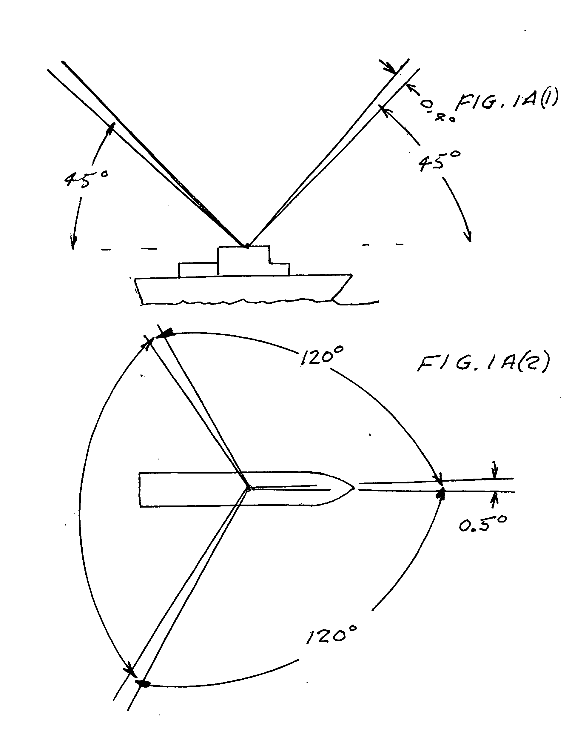
[0030] A first preferred embodiment of the present invention is shown in FIGS. 1A(1) and 1A(2). This is a stellar imaging system useful for day and night accurate stellar navigation for ships. The system is a “strap down” system (i.e., it is mounted or “strapped down” on a platform, in this case a ship) with no moving parts. Three telescopes, separated by 120 degrees in azimuth and directed at 45 degrees in elevation, provide images of stars on three infrared 256×320 pixel cameras designed for operation in the infrared waveband at about 1.6 micron wavelength. The instantaneous field of view of each camera is 0.4×0.5 degrees, which provides a very high probability of imaging stars that are recognized by a computer system programmed with special algorithms, a star catalog, and star pattern recognition software. The camera is a fast frame rate camera operating at frame rates up to 30 Hz with a full well capacity of 5 million electrons, with thermoelectric cooling.

[0031] A second prefe...


PUM


Abstract

An automatic celestial navigation system for navigating both night and day by observation of K-band or H-band infrared light from multiple stars. A preferred embodiment uses three telescopes with each of the three telescopes rigidly mounted with respect to each other and rigidly mounted on a movable platform such as a ship or airplane with each telescope being directed at a substantially different portion of sky. Telescope optics focuses, onto the pixel array of a sensor, H-band or K-band light from stars in the field of view of each telescope. The system also includes an inclinometer, an accurate timing device and a computer processor having access to cataloged infrared star charts. The processor is programmed with special algorithms to use image data from the infrared sensors, inclination information from the inclinometer, time information from the timing device and the cataloged star charts information to determine positions of the platform. At least two telescopes pointed far enough from the sun detect stars. Direction information from two stars is needed for locating the platform with respect to the celestial sphere. The computer is also preferably programmed to use this celestial position information to calculate latitude, longitude and absolute azimuth, all of which may be displayed on a display device such as a monitor. In a preferred embodiment each of the three telescopes are fixed on a moving ship and views a 0.5×0.4 degree region of the sky for H-band starlight from stars with brightness greater than 6.4 H-band magnitude. Located stars are then compared with star positions from the star catalog within a selected 5×5 degree region of the sky. A correlation of the data from the three telescopic measurements determines the position of the ship to a precision of 30 meters.

Description

[0001] This application claims the benefit of Provisional Application Ser. No. 60 / 619,858, filed Oct. 18, 2004.FIELD OF INVENTION [0002] This invention relates to stellar imaging systems and in particular to such systems useful for position location and platform attitude determination. BACKGROUND OF THE INVENTION [0003] Global positioning systems (GPS) are widely used for navigating ships and aircraft. However, these systems are vulnerable and have other shortcomings. Their space components are subject to hostile attack and the systems may be jammed. The systems also suffer from reliability failures and these GPS systems do not provide absolute azimuth positioning needed for attitude determination. Inertial navigation systems (INS) mitigate GPS deficiencies; however, these inertial navigation systems are not accurate over long time periods. Errors may accumulate at rates of about an arc-sec per hour to an arc-min per hour. Periodic alignment of the inertial navigation systems is req...

Claims


Application Information

Patent Timeline
IPC IPC(8): G01C21/00
CPCG01C21/025
Inventor BELENKII, MIKHAILBRUNS, DONALD G.RYE, VINCENT A.BRINKLEY, TIMOTHY
Owner TREX ENTERPRISES CORP
Learn More