
Image forming device and mounting member for mounting a toner container thereon

Active Publication Date: 2006-04-20
RICOH KK
View PDF23 Cites 51 Cited by
  • Summary
  • Abstract
  • Description
  • Claims
  • Application Information

AI Technical Summary

Benefits of technology

[0009] A first object of the present invention is to provide an image forming device and mounting member for mounting a toner container thereon whereby mounting and releasing thereof is very easily performed while ensuring visibility of the entire toner container, yet wherein costs can be kept low.
[0010] A second object of the present invention is to provide an image forming device wherein secure mounting of the toner container in the main unit of the image forming device can be verified electrically.
[0011] A third object of the present invention is to provide an image forming device wherein the connector terminal can be protected so that the connector terminal of the data processing unit provided in the main unit of the image forming device is not deformed, damaged or destroyed, when the toner container is mounted in the main unit of the image forming device.

Problems solved by technology

Consequently, in an image forming device comprising a mounting member in this system, in arranging the mounting / releasing side of the toner container adjacent to a wall or pillar or the like, the direction of installation and / or the location of installation thereof is restricted by the fact that this mounting member may interfere with mounting / release of the toner container.
Since the toner container is mounted / released from the direction of the axis of rotation, it is difficult to see the mounting section because of the toner container and if for example the hand of the operator shakes when effecting mounting / release operation, positional location in the mounting position is difficult.
This therefore adversely affects ease of mounting and for example some mechanism for holding / fixing the toner container in the mounted position becomes necessary, leading to the problem of increased costs.
However, if the connector terminal that is used to effect electrical connection between the toner container and the main unit is deformed by some external force from outside, a poor connection may result.
However, no means for preventing deformation or damage or destruction (for example deformation of the connector terminal) of this electrical connection caused by unwanted external force is disclosed.
However, no means for preventing deformation or damage or destruction of the electrical connection of this intermediate connector and the ID chip is disclosed.

Method used


Image

  • Image forming device and mounting member for mounting a toner container thereon
  • Image forming device and mounting member for mounting a toner container thereon
  • Image forming device and mounting member for mounting a toner container thereon

Examples


Embodiment Construction

[0044] Embodiments of the present invention are described in detail below with reference to the drawings.

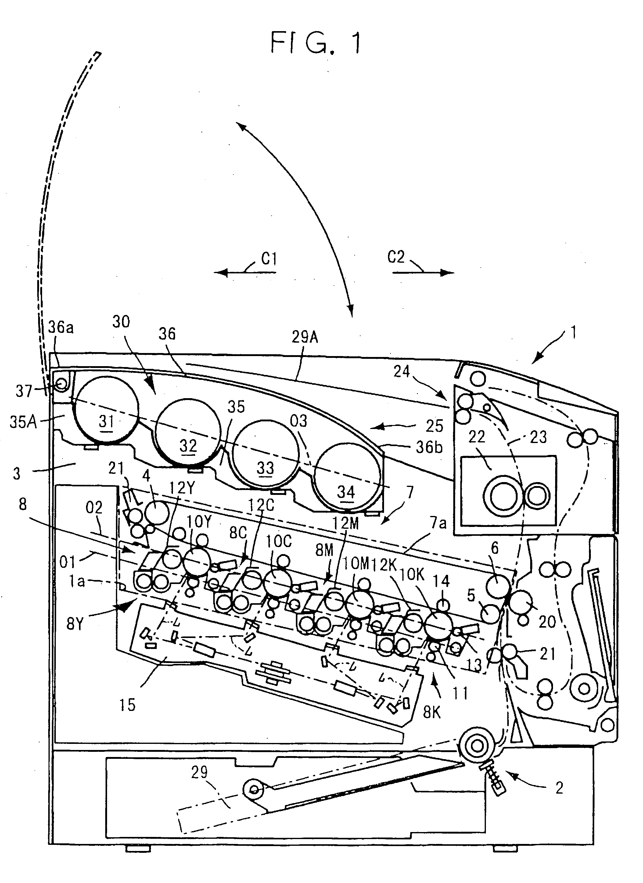
[0045] An image forming device according to this embodiment is a color printer (hereinbelow termed a “printer”) capable of forming a full-color image, in which the tandem arrangement is adopted. The image forming device is not restricted to the printer shown in FIG. 1 but could be for example a copier, facsimile machine or machine combining these functions.

[0046] First of all, the basic construction of a printer and its operation will be described with reference to FIG. 1 and then the construction and operation peculiar to this embodiment will be described.

[0047] In this printer, a paper feed unit 2 in which the paper 29 constituting the recording medium is accommodated is arranged below the device main unit 1 and an image forming unit 3 is arranged thereabove. The image forming unit 3 comprises an image creation section 8 comprising four image creation units 8Y, 8C, 8M, 8K co...


PUM


Abstract

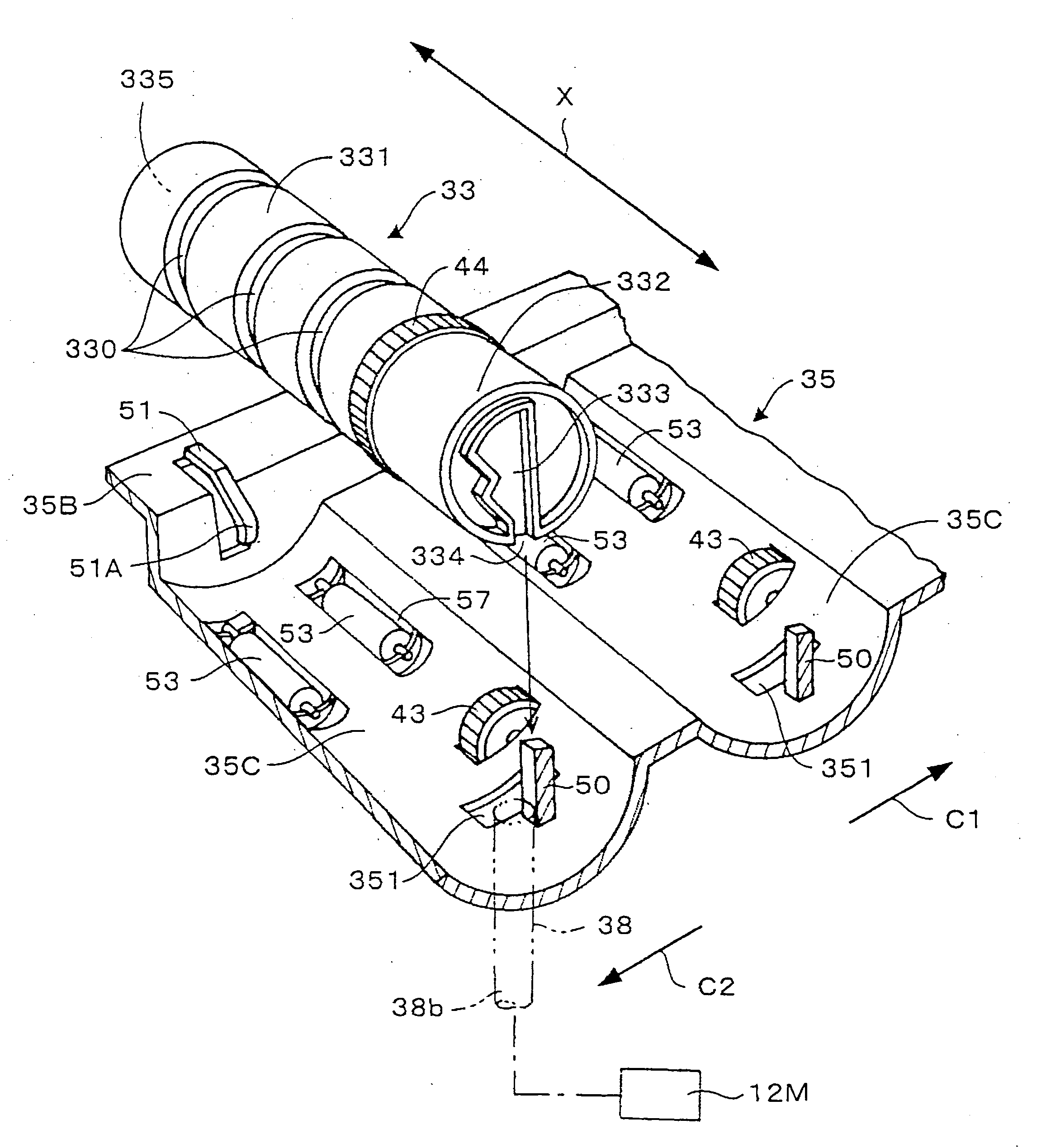
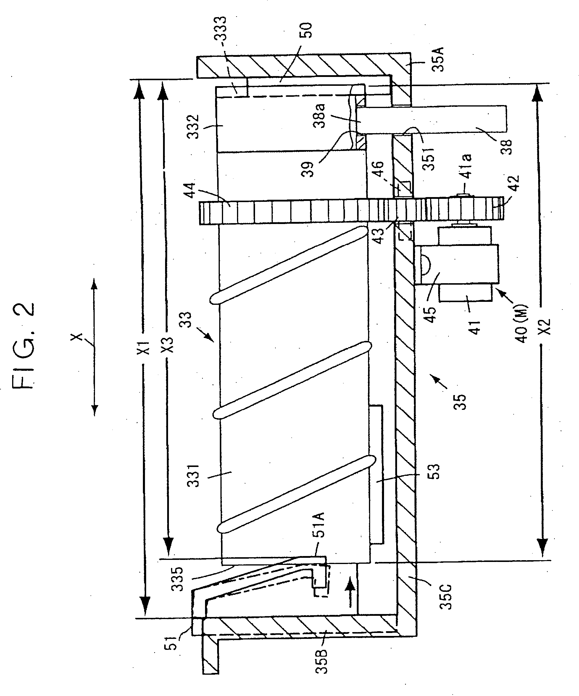
A toner container mounting member comprises mounted thereon a plurality of toner containers that perform supply of toner by being themselves rotated. The toner containers are laid in the same direction to be mounted / released from above; a plurality of guiding members that rotatably support the toner containers are integrally formed.

Description

BACKGROUND OF THE INVENTION [0001] 1. Field of the Invention [0002] The present invention relates to an image forming device such as an electrophotographic type copier, printer, a facsimile machine or machine combining these functions and in particular relates to a mounting member for mounting toner containers such as toner bottles that accommodate toner constituting developer on an image forming device. [0003] 2. Description of the Related Art [0004] As disclosed for example in Laid-open Japanese Patent Application No. 2002-139905, in one recent type of image forming device, toner supply action from a toner container such as a toner bottle wherein the toner that supplies a developing device is accommodated is performed by discharging toner from within the bottle to the outside from a toner supply port by rotating the bottle itself. Such a toner container is formed in a cylindrical shape extending in the direction of the axis of rotation thereof, and is formed in its outer surface w...

Claims


Application Information

Patent Timeline
IPC IPC(8): G03G15/08
CPCG03G2215/0678G03G2221/163G03G15/0872G03G21/1676G03G15/0863G03G21/1647
Inventor UCHIYAMA, MISAKIKUMA, KAZUOSATSUDA, KIYONORIISHII, HIROSHINOGUCHI, YUUSUKEKIKURA, MAKOTOFUKUCHI, YUTAKASUZUKI, KAZUKI
Owner RICOH KK
Learn More