Two-way ranging between radio transceivers

a radio transceiver and two-way ranging technology, applied in direction finders, instruments, synchronisation arrangements, etc., can solve the problems of increasing system complexity and overhead, too large estimated distances,

Active Publication Date: 2006-04-20
MITSUBISHI ELECTRIC RES LAB INC
View PDF7 Cites 15 Cited by
  • Summary
  • Abstract
  • Description
  • Claims
  • Application Information

AI Technical Summary

Problems solved by technology

Therefore, the estimated distance is too large.
However, the estimation of the arrival time is different from the true arrival time by a time offset toff,2, which is because

Method used


Image

  • Two-way ranging between radio transceivers
  • Two-way ranging between radio transceivers
  • Two-way ranging between radio transceivers

Examples


Embodiment Construction

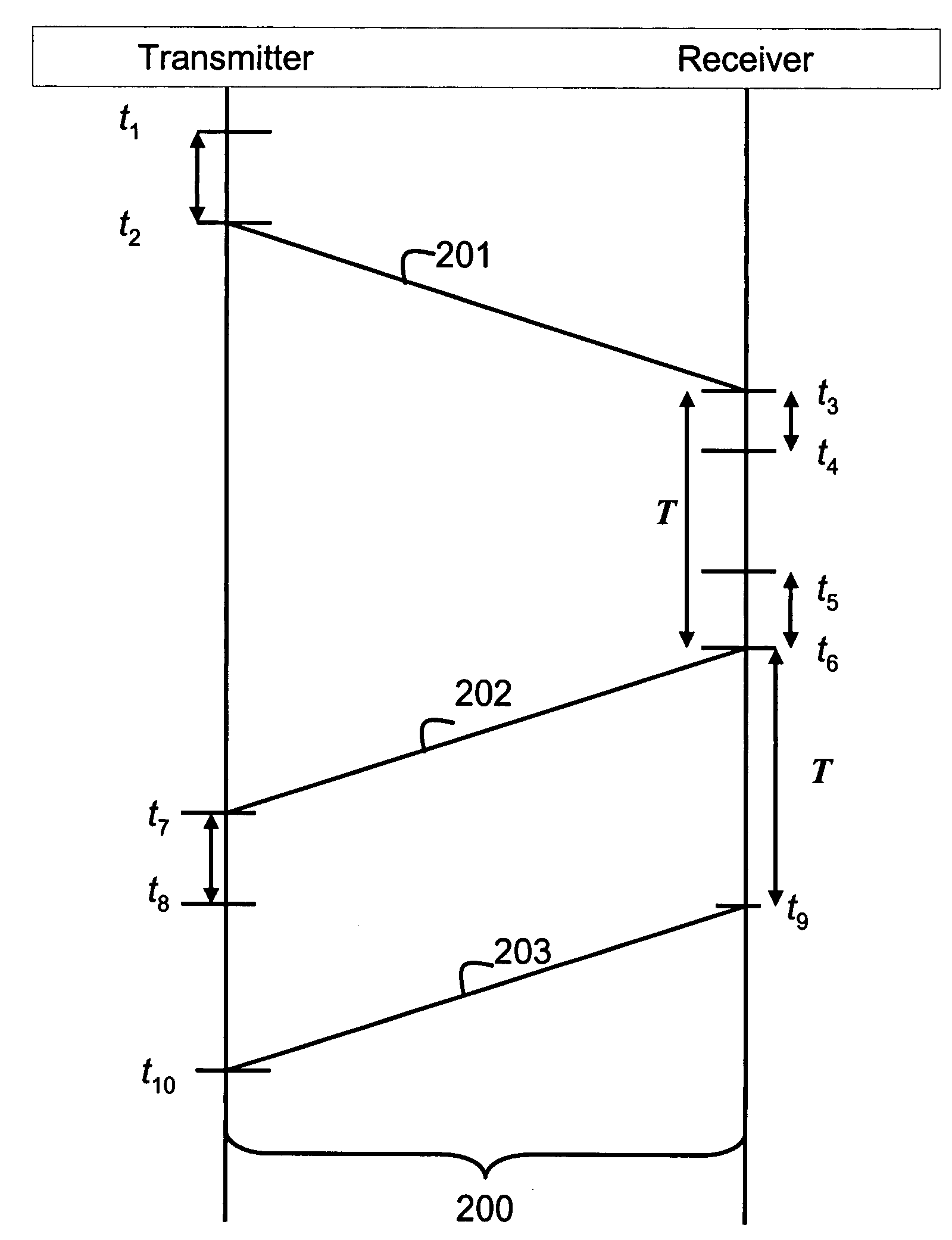
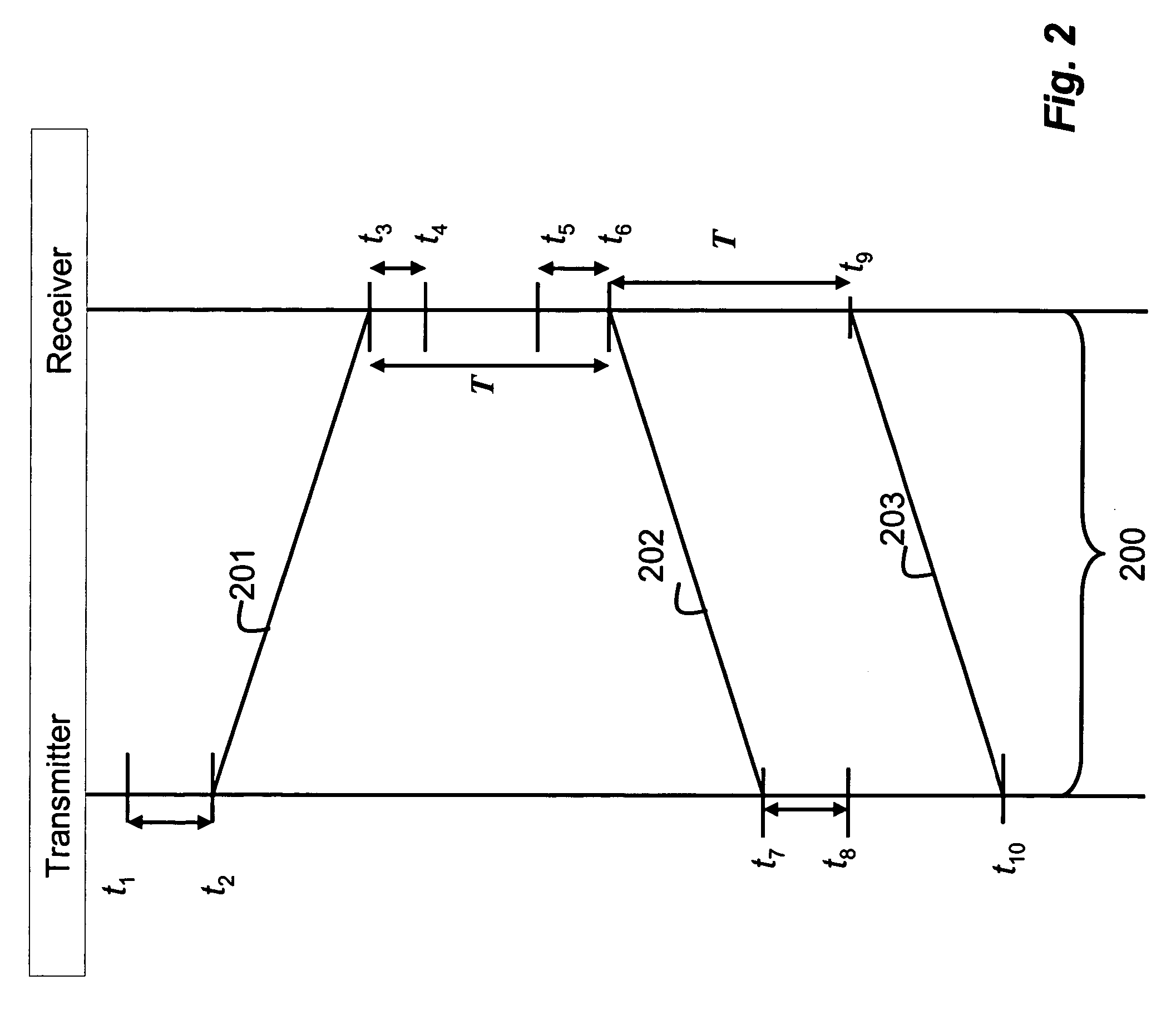
[0012] Our invention provides two-way ranging for estimating a distance between two radio transceivers in a wireless communications network. For the purpose of this description, a first transceiver that determines the distance is called the transmitter, and a second transceiver that participates in the distance estimate is called the receiver. However, it should be understood that both devices can transmit and receive for the operation of the invention, which uses two-way ranging.

[0013] In contrast with the prior art, we do not transmit additional information to correct for processing delays. We can also estimate drift rates between clocks of the transceivers.

[0014] As shown in FIG. 2, t1, t2, t7, t8, and t10 denote times according to local clock at the transmitter, and t3, t4, t5, t6, and t9 denote times at the receiver.

[0015] At time t1, the transmitter prepares to transmit a signal 201 to the receiver. The signal enters the channel 200 at time t2, due to a processing delay |t1...


PUM


Abstract

A method estimates a distance between transceivers in a wireless communications network. A first time interval T is set in a transmitter and a receiver. A signal is transmitted from the transmitter to the receiver at a time t2 according to a first clock of the transmitter. The signal is received in the receiver at a time t3. Processing delays of the receivers are determined. A reply to the signal is sent from the receiver to the transmitter at a time t6 such that |t3−t6|=T. The reply is received in the transmitter at a time t7 of the first clock and a distance d between the transmitter and the receiver is determined according to d=c(|t2−t7|−T)/2, where c is the speed of light.

Description

FIELD OF THE INVENTION [0001] The present invention relates generally to radio communication systems, and more particularly to determining distances between transceivers. BACKGROUND OF THE INVENTION [0002] To estimate a distance between a transmitter and a receiver in a wireless communications network, the transmitter can send a signal to the receiver at t1. The receiver, as soon as possible, returns a reply signal to the transmitter. The transmitter measures the time of arrival (TOA) of the reply signal at time t2. An estimate of the distance between the transmitter and the receiver is the time for the signal to make the round trip divided by two and multiplying by the speed of light, i.e.: D=t1-t22⁢c. This simple method ignores possible delays at the transmitter and the receiver. Therefore, the estimated distance is too large. [0003]FIG. 1 shows a better method for estimating the distance, see W. C. Lindsey and M. K. Simon, “Phase and Doppler Measurements in Two-Way Phase-Coheren...

Claims


Application Information

Patent Timeline
IPC IPC(8): H04L7/00
CPCH04W56/0075
Inventor GEZICI, SINANSAHINOGLU, ZAFER
Owner MITSUBISHI ELECTRIC RES LAB INC
Why Eureka
Try Eureka