
Producing method of rubber strip winding body, and rubber strip winding apparatus

a winding body and winding technology, which is applied in the direction of tyres, domestic applications, other domestic articles, etc., can solve the problems of deteriorating tire uniformity, large torsion and error, and deteriorating quality and precision of winding bodies, so as to enhance winding precision, reduce torsion of rubber strips, and improve quality

Inactive Publication Date: 2006-04-20
SUMITOMO RUBBER IND LTD
View PDF8 Cites 16 Cited by
  • Summary
  • Abstract
  • Description
  • Claims
  • Application Information

AI Technical Summary

Benefits of technology

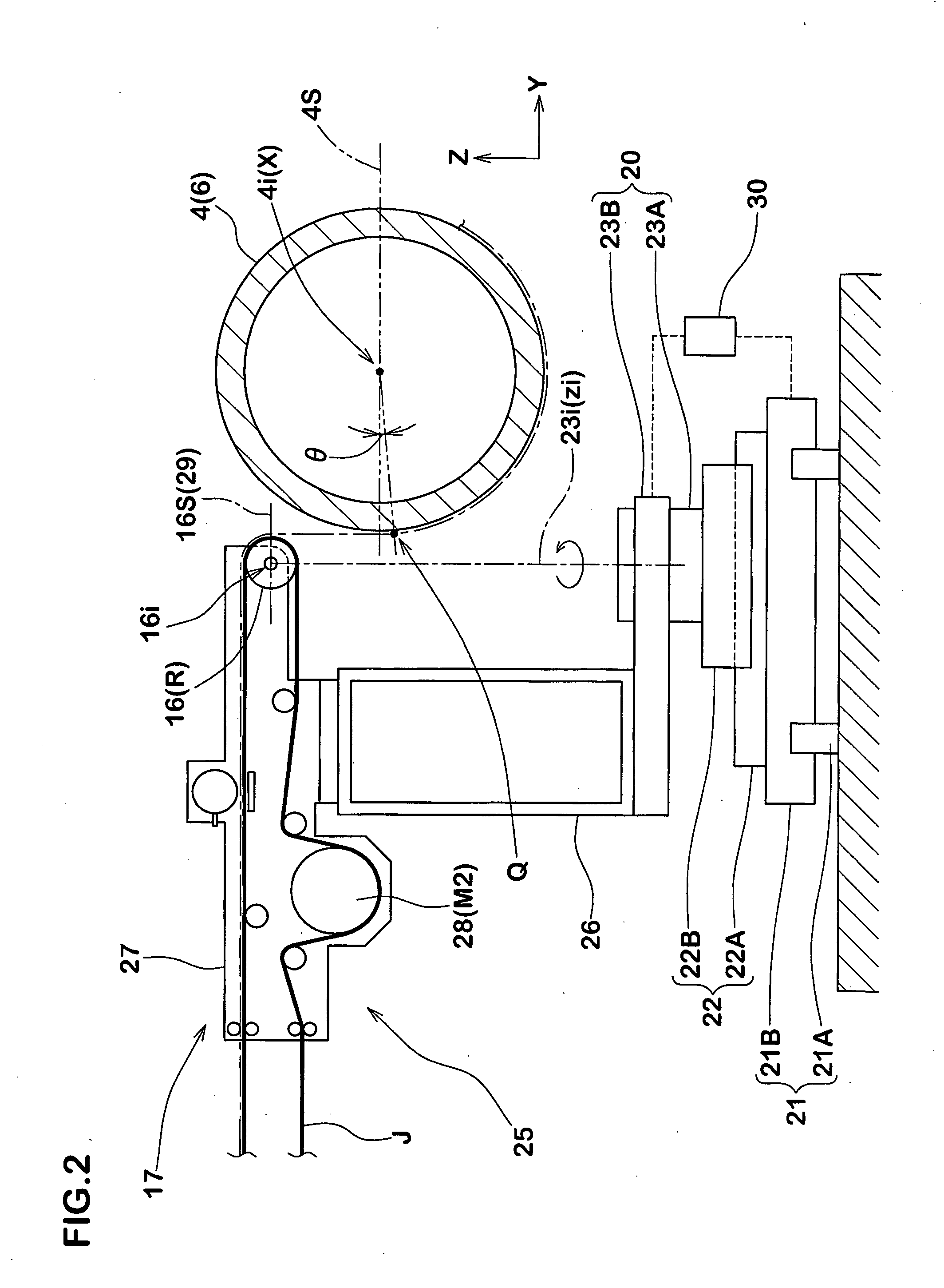
[0011] Hence, based on a structure in which the sending-out roller is laterally moved while changing the inclination angle of the axis of the sending-out roller, it is an object of the present invention to provide a producing method of a rubber strip winding body, and a rubber strip winding apparatus capable of suppressing torsion of the rubber strip, capable of enhancing the winding precision, and capable of forming a high quality and high precision winding body having a cross section closer to the target stably.
[0022] Since the present invention has the above-described structure, it is possible to suppress torsion of the rubber strip, to enhance the winding precision, and to form a high quality and high precision winding body having a cross section closer to the target stably.

Problems solved by technology

As a result, there is a problem that the target cross section shape of the winding body (d) is warped, and this deteriorates the quality and precision of the winding body (d), a defect such as bare is generated in a vulcanized tire surface, and tire uniformity is deteriorated.
When the cylindrical body (c) has non-linear cylindrical contour shape, if the rubber strip (b) is wound around the outer peripheral surface of the cylindrical body (c), large torsion and error are generated in the rubber strip (b), and there is a problem that the quality and precision of the winding body (d) are deteriorated.

Method used


Image

  • Producing method of rubber strip winding body, and rubber strip winding apparatus
  • Producing method of rubber strip winding body, and rubber strip winding apparatus
  • Producing method of rubber strip winding body, and rubber strip winding apparatus

Examples


example tire b

OF THE PRESENT INVENTION

[0075] Using the rubber winding apparatus, winding body for a tread rubber of a tire for an automatic two-wheeled vehicle was formed in accordance with the specification shown in Table 2. Using the winding body, tires for an automatic two-wheeled vehicle having tire size of 190 / 55R17 were prototyped, and a generation status of defects on an outer surface and a uniformity of the tires were compared and evaluated.

[0076] The former has a drum-like contour shape, and a difference of a diameter DC at its central portion and a diameter Ds at its each of opposite ends was 120 mm, and a width of the former was 185 mm. In a conventional example B1 and an example tire B1 of the present invention, a bisector point No thereof laterally moves through a running line (straight line) which is in parallel to the axis 4i of the former. In an example tire B2 of the present invention, a bisector point No of the sending-out roller 16 laterally moves through a running line (conve...


PUM

PropertyMeasurementUnit
inclination angleaaaaaaaaaa
angleaaaaaaaaaa
angleaaaaaaaaaa

Abstract

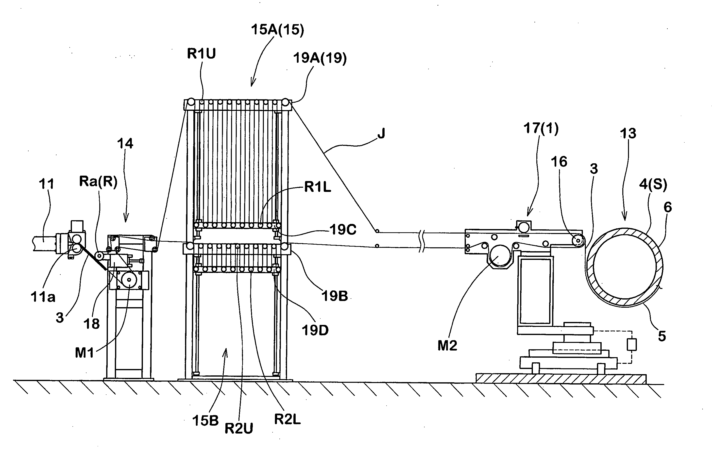
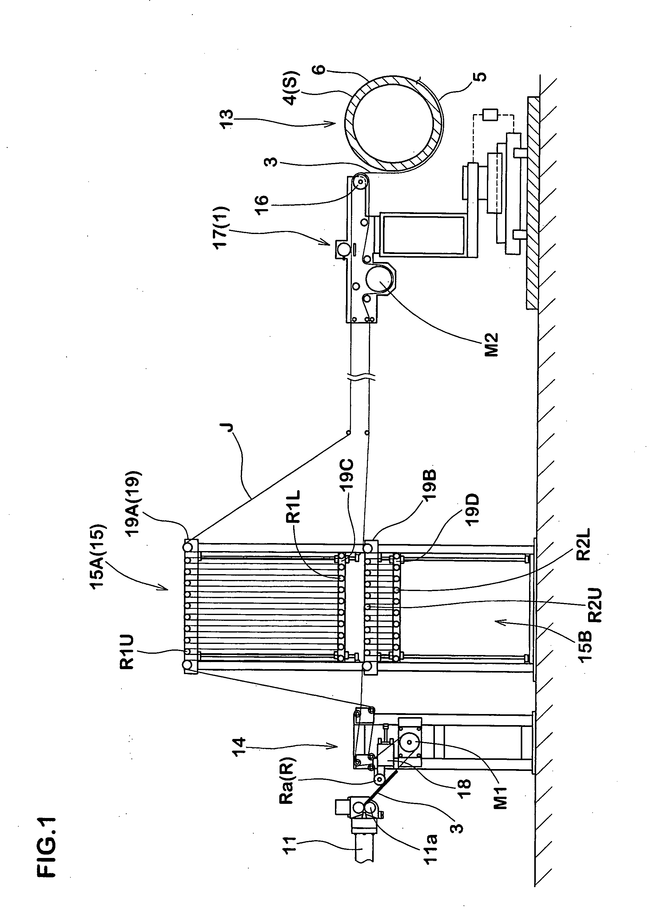
An unvulcanized rubber strip (3) is supplied to an outer peripheral surface of a rotating cylindrical body (4) from a sending-out roller (16) which laterally moves in an axial direction of the cylindrical body (4), thereby spirally winding the rubber strip (3) to form a winding body (5). In a tilting reference plane (29) defined as a plane which is in parallel to a plane (4S) passing through an axis (4i) of the cylindrical body (4) and which passes through an axis (16i) of the sending-out roller (16), the sending-out roller (16) is held such that the sending-out roller (16) can tilt positively and negatively within an inclination angle (α) of 0 to 45° with respect to a tilting reference line (N) which is parallel to the axis (4i) of the cylindrical body (4). The sending-out roller (16) is laterally moved while changing the inclination angle (α).

Description

BACKGROUND OF THE INVENTION [0001] 1. Field of the Invention [0002] The present invention relates to a producing method of a rubber strip winding body, and a rubber strip winding apparatus capable of enhancing precision and quality of a winding body formed by spirally winding a rubber strip around a cylindrical body. [0003] 2. Description of the Related Art [0004] As a pneumatic tire is required to show different characteristics depending on the part, it is composed of various rubber members such as a tread rubber, a sidewall rubber, a clinch rubber, a breaker cushion rubber, an inner liner rubber and the like having different compositions and cross sections. [0005] In recent years, it is proposed to form various kinds of tire rubber members that are formed by winding the rubber strip spirally using a so-called strip wind method. See Japanese Patent Application Laid-open No.2000-94542. [0006] In the case of this strip wind type, as roughly shown in FIG. 10, when an unvulcanized rubb...

Claims


Application Information

Patent Timeline
Patent Type & Authority Applications(United States)
IPC IPC(8): B29D30/08
CPCB29D30/30B29D30/60
Inventor HAYASHI, NORIOONIMATSU, HIROYUKIMIKI, YOUJIRO
Owner SUMITOMO RUBBER IND LTD
Learn More