
Pivotal and rotational connection for a vacuum cleaner tool

a vacuum cleaner and tool technology, applied in the direction of suction cleaners, suction hoses, domestic applications, etc., can solve the problems of high cost, trouble, and relative complexity of many different joint or connection structures that have become known in the art, and achieve the effect of long trouble-free operating life and high reliability

Active Publication Date: 2006-04-20
STEIN
View PDF1 Cites 25 Cited by
  • Summary
  • Abstract
  • Description
  • Claims
  • Application Information

AI Technical Summary

Benefits of technology

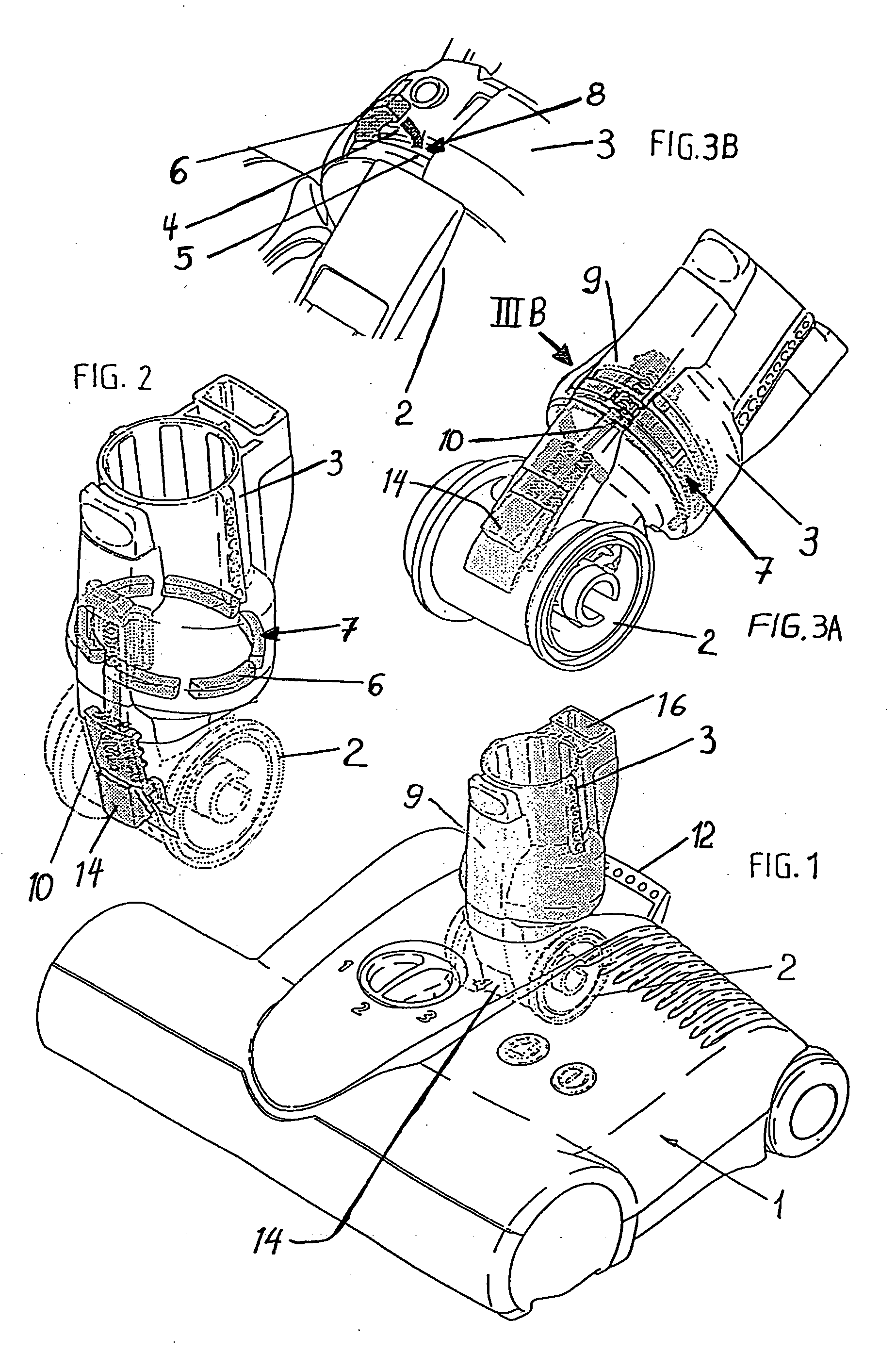
[0009] The inventive pivotal and rotational connection is simple and robust, and can be easily assembled or disassembled simply by inserting or removing the partial ring segment elements through the provided opening into or from the circumferential channel formed by the grooves of the overlapping and inter-engaging coupling ends of the pivot element and the rotation element. The achieved connection ensures relatively small axial play yet smooth free rotation between the connected pivot element and rotation element. The pivot element and rotation element can be economically produced of a plastic, for example by any conventionally known molding processes. The partial ring segment elements forming the guide and connection ring can be produced of a metal, or a plastic, for example a low-friction plastic.
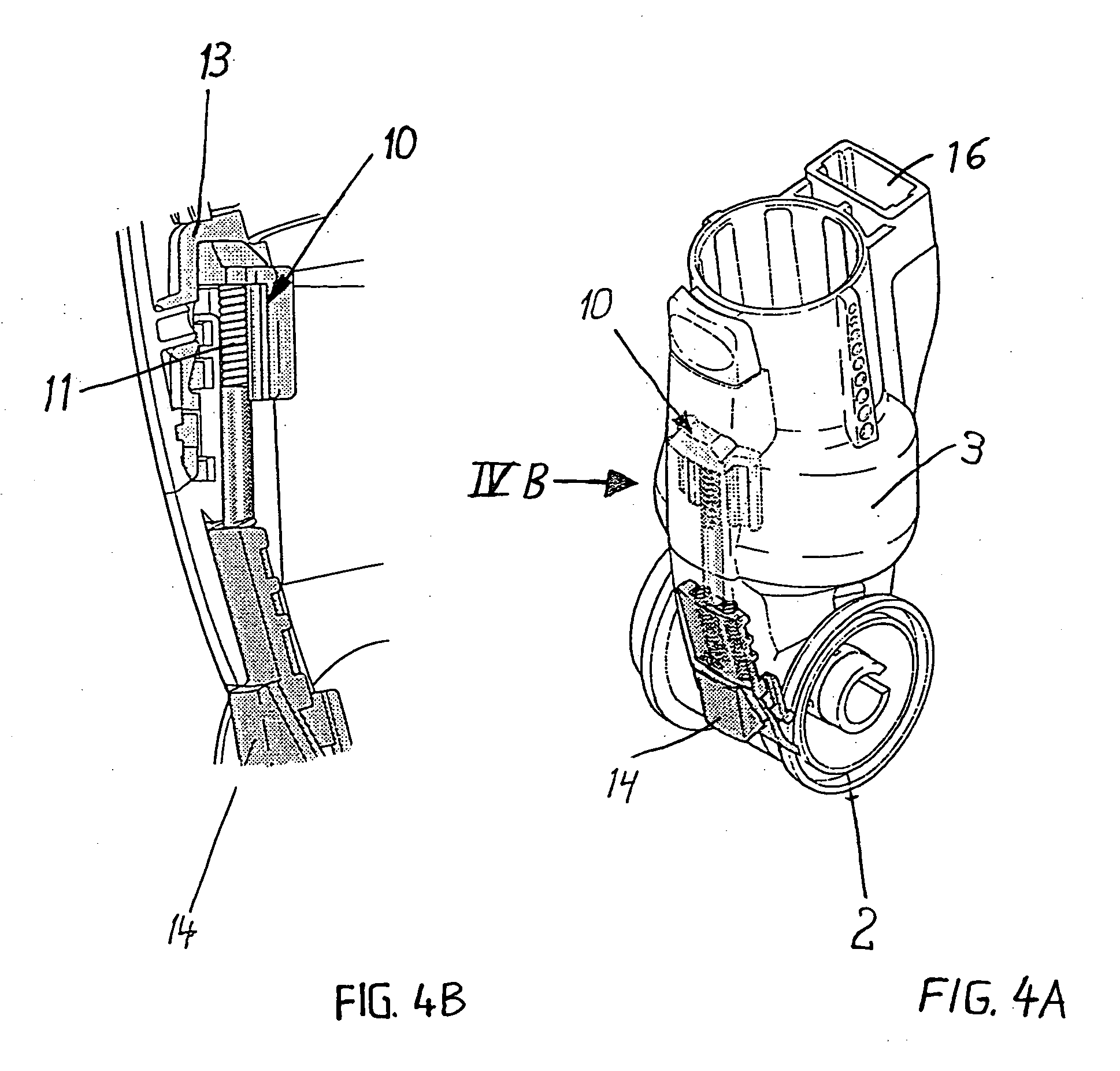
[0014] A vacuum passage communicates continuously through the interior of the rotation element and the pivot element, to establish a continuous vacuum duct from the vacuum port of the vacuum cleaner (e.g. the vacuum wand, hose, handle or the pipe stub forming the suction port of a handheld vacuum cleaner, or the like) through the connection arrangement into the suction opening of the suction tool. Moreover, if the suction tool is a motorized power brush or the like, requiring an electrical power supply to an electric motor thereof, then electrical conductor lines are further provided through or along the connection arrangement between the vacuum cleaner and the suction tool. In this regard, a pocket-shaped interspace or cavity is preferably provided in and between the pivot element and the rotation element, so as to movably receive the electrical conductor lines therein. Such an arrangement allows the relative (partial) rotation of the rotation element and the pivot element, without disrupting the electrical conductor lines.

Problems solved by technology

It has been found in practice that it is relatively complicated, costly, and trouble-prone to achieve a pivotal and rotational connection of a suction tool to a vacuum cleaner.
The problems in this regard involve several factors.
The many different joint or connection structures that have become known in the art have not been sufficiently durable and robust to achieve a long trouble-fee operating life without failure of the plastic components, while achieving the necessary force transmission between the connected suction tool and vacuum cleaner wand, handle or the like.

Method used


Image

  • Pivotal and rotational connection for a vacuum cleaner tool
  • Pivotal and rotational connection for a vacuum cleaner tool
  • Pivotal and rotational connection for a vacuum cleaner tool

Examples


Embodiment Construction

[0024] In the illustrated example embodiment (see FIGS. 1 and 5), an inventive pivotal and rotational connection arrangement establishes a pivotal and rotational connection between a suction tool 1 such as a vacuum cleaner floor cleaning brush, and a vacuum port such as the free end of a suction wand 15 of a vacuum cleaner. The pivotal and rotational connection arrangement includes a pivot element 2 that is pivotally connected to the suction tool 1, and a rotation element 3 that is rotatably connected to the pivot element 2. To establish this rotatable connection or coupling between the pivot element 2 and the rotation element 3, respective coupling ends of the elements 2 and 3 are inserted one in the other and are rotatably secured as will be described below. In the illustrated embodiment, the cylindrical sleeve or collar-shaped coupling end of the pivot element 2 is inserted into the cylindrical sleeve or collar-shaped coupling end of the rotation element 3. However, that arrangem...


PUM


Abstract

A connection arrangement between a vacuum cleaner and a suction tool includes a pivot element pivotably connected to the suction tool and a rotation element rotatably coupled to the pivot element. A suction wand, hose, handle or other vacuum port of the vacuum cleaner is removably connected to a connection end of the rotation element. Coupling ends of the pivot and rotation elements are inserted one in the other, and respectively have circumferential grooves that form a circumferential channel therebetween. Plural partial ring segment elements are received in the circumferential channel to form a connection ring that rotatably secures the pivot and rotation elements. The ring segment elements are inserted into or removed from the channel through a selectively coverable opening in the rotation element or the pivot element. A catch cooperates with a detent to hold a vertically pivoted, rotationally centered rest position of the components.

Description

PRIORITY CLAIM [0001] This application is based on and claims the priorities under 35 U.S.C. §119 of German Patent Application 10 2004 050 471.7, filed on Oct. 16, 2004, and German Patent Application 10 2004 052 306.1, filed on Oct. 28, 2004, the entire disclosures of which are incorporated herein by reference. FIELD OF THE INVENTION [0002] The invention relates to an arrangement for establishing a pivotal and rotational connection of a vacuum cleaner suction tool to a suction wand, hose, handle, or other suction port of a vacuum cleaner. BACKGROUND INFORMATION [0003] For convenient handling and flexible or adaptable functionality, it is desirable to connect a vacuum cleaner suction tool in a pivotal and rotational manner relative to the suction wand, hose, handle or other vacuum port connection of a vacuum cleaner. Such a vacuum cleaner suction tool may, for example, be a carpet cleaning power brush or a floor cleaning suction head or any other type of tool, implement, accessory or...

Claims


Application Information

Patent Timeline
IPC IPC(8): A47L9/04
CPCA47L9/02
Inventor STEIN, THOMAS
Owner STEIN
Learn More