
System and method for monitoring and responding to device conditions

a technology for monitoring and responding to the condition of the device, applied in the direction of instruments, electrographic process equipment, electrical appliances, etc., can solve the problems of increasing complexity, significant equipment downtime, inconvenience, cost, etc., and achieve the effect of easy follow-up and performan

Inactive Publication Date: 2006-04-13
MULLIN TERENCE J
View PDF34 Cites 71 Cited by
  • Summary
  • Abstract
  • Description
  • Claims
  • Application Information

AI Technical Summary

Benefits of technology

"The patent describes a system that can monitor devices, detect errors, and provide easy-to-use instructions to users. The system receives a signal indicating a device condition and accesses a database to determine if a response is needed. If a response is needed, the system provides instructional media to the user interface at or adjacent to the device. The system can also monitor multiple devices and deliver context-appropriate instructional information to the user interface. The technical effect of the patent is to provide a convenient and efficient way to monitor and troubleshoot devices remotely."

Problems solved by technology

Such devices are making more and more use of high technology, and tend to become more and more complex as technology advances.
Although these devices usually work quite well and provide important benefits, inevitably they will occasionally develop errors in operation and / or require certain maintenance, or a user may need guidance in use of the device.
This can result in significant equipment downtime, inconvenience, and cost.
However, such instruction manuals are typically very difficult to read, and often are misplaced by users.
When a problem occurs with a device, the user typically must spend exorbitant amounts of time just to locate the appropriate pages of the instruction manual, if the manual can be located, and then must invest substantial effort figuring out how to apply the instruction manual text to the actual problem.
This leads to wasted time and frustration, as well as increased downtime for the device.
However, experience has proven such instructions to often be incomplete and / or difficult to follow, and users may simply walk away from the machine rather than solve the problem because of the difficulty associated therewith.
Further, technology is advancing at astronomical rates, and the workforce cannot keep pace with the advances in technology in connection with all of the devices that users typically encounter.
Thus, users that are not trained on the intricacies of the equipment are relying upon such equipment, and when called upon to fix even minor errors or address maintenance needs for such equipment, the users likely are incapable and / or unwilling to address such issues.

Method used


Image

  • System and method for monitoring and responding to device conditions
  • System and method for monitoring and responding to device conditions
  • System and method for monitoring and responding to device conditions

Examples


Embodiment Construction

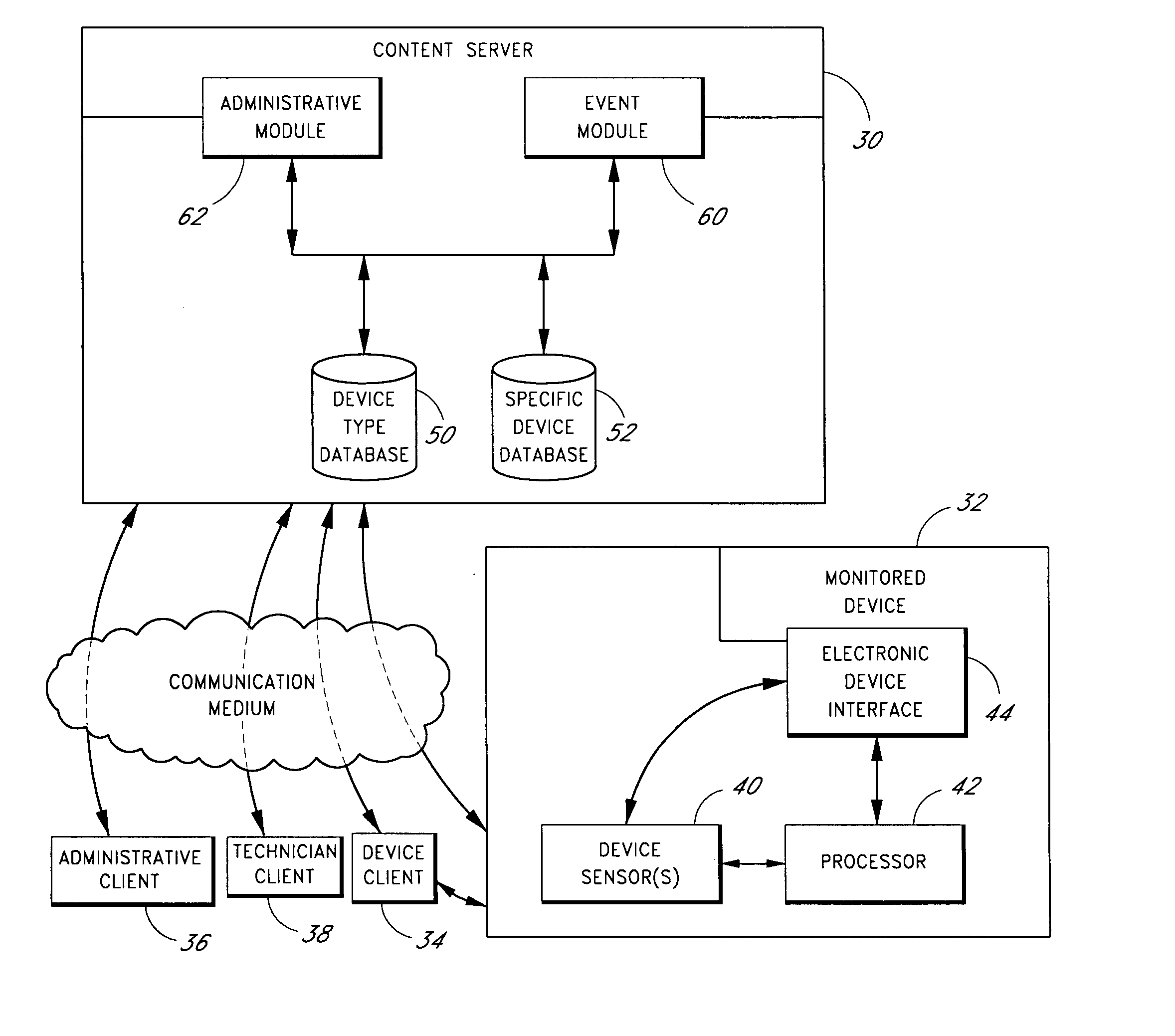
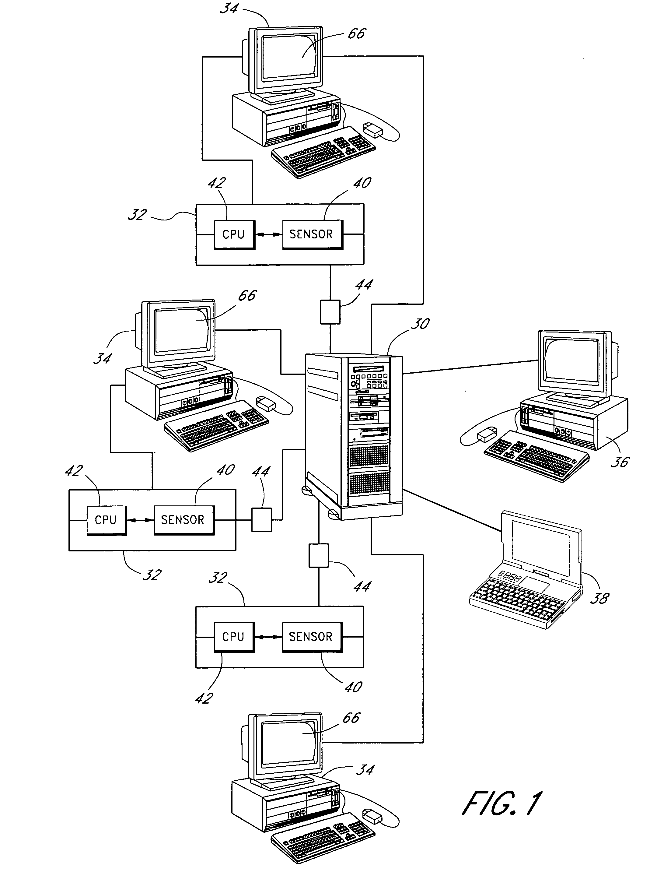
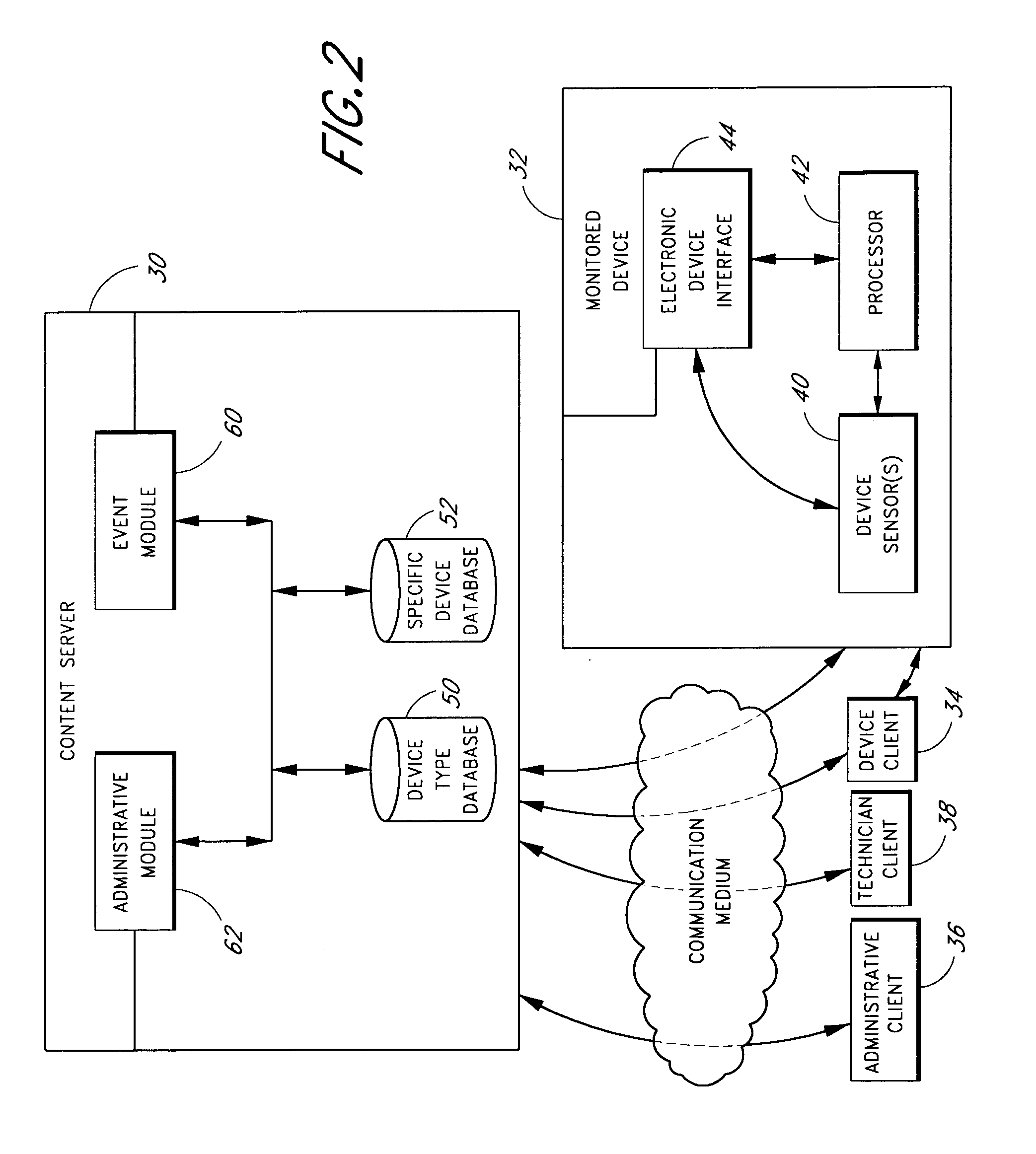
[0026] With reference first to FIG. 1, a relatively simple device network is illustrated. In the illustrated embodiment, a content server 30 is electronically connected to a plurality of electromechanical devices 32, a corresponding plurality of device clients 34, an administrative client 36 and a technician client 38.

[0027] In this specification, the term “electromechanical device” is a broad term that includes, without limitation, any device having some mechanical mechanism or interface, and which includes at least one sensor capable of electronically detecting and communicating certain device conditions. Examples of electromechanical devices include computer printers, copiers, laboratory analysis devices, and automated manufacturing machinery. It is to be understood that such devices need not be originally manufactured with the sensors, but sensor(s) may be added in order to detect and electronically monitor certain conditions.

[0028] Throughout this specification, the term “ser...


PUM


Abstract

A system and method for monitoring and responding to device conditions is provided. A content server monitors sensed conditions of a device. Upon detection of an action-triggering condition, such as an error in the device, the content server accessed databases containing information pertaining to the monitored device in order to determine the nature of the error. When the error is identified, a database including a library of instructional content is accessed and the content server selects appropriate instructional content to enable a user to resolve the issue that prompted the error condition. Once the content server has chosen the correct instructional media, the content is delivered to a device client comprising a display screen at or adjacent the monitored device. Preferably, the instructional media comprises full motion video so that the device user simply copies what is seen on the display in order to resolve the issue. Action-triggering conditions can also include issues such as maintenance needs, training conditions, and user help requests.

Description

CROSS-REFERENCE TO RELATED APPLICATIONS [0001] This application claims priority to U.S. Provisional Application No. 60 / 618,197, which was filed on Oct. 12, 2004, the entirety of which is hereby incorporated by reference.BACKGROUND OF THE INVENTION [0002] 1. Field of the Invention [0003] The present invention is in the field of managing devices having condition sensors. More specifically, the present invention relates to monitoring such devices and delivering appropriate instruction in real time to device users as needed. [0004] 2. Description of the Related Art [0005] Today's society is increasingly dependent upon highly technical labor-saving devices. Such devices include, for example, copy machines, computers, computer printers, scanners, telephones, film processors, laboratory analytical equipment, automobiles and the like. Such devices are making more and more use of high technology, and tend to become more and more complex as technology advances. Although these devices usually ...

Claims


Application Information

Patent Timeline
Patent Type & Authority Applications(United States)
IPC IPC(8): G09B19/00
CPCG03G15/5016G03G15/55G09B7/02G09B19/0053H04N1/00002H04N1/00037H04N1/00042H04N1/00061H04N1/00344H04N1/00408H04N1/00503H04N1/32625H04N1/32662G03G2215/00109G03G15/5079G06Q10/06315
Inventor MULLIN, TERENCE J.
Owner MULLIN TERENCE J
Learn More