
Disk array system

a technology of array system and disk array, which is applied in the field of disk array system, can solve the problems of high risk of data loss due to hdd failure, deterioration of cost performance, and high early failure rate of hdd

Inactive Publication Date: 2006-04-13
HITACHI LTD
View PDF16 Cites 45 Cited by
  • Summary
  • Abstract
  • Description
  • Claims
  • Application Information

AI Technical Summary

Benefits of technology

The present invention provides a technology for securing data reliability in an early failure period of a disk array system. The technology utilizes unused regions of a storage device for data backup and prevents data loss due to failure of a hard disk drive (HDD) in the early failure period. The controller of the disk array system divides the data into two parts and performs a parity process to provide control in accordance with the RAID control system. The technology is applicable to both manufacturer and user levels and can prevent data loss during an early failure period of the disk array system.

Problems solved by technology

An early failure rate of a HDD is generally high, and further, a risk of data loss due to a HDD failure becomes higher when the number of HDDs included in the same RAID group in the case of a disk array system is increased.
However, if the disk array system is arranged with only data reliability taken into account, its cost performance is deteriorated.
Further, on the side of manufacturer, it is actually difficult to take avoidance measures in terms of inspection space and facility costs.
For these reasons, it can be said that the risk for the early failures of the products is high.
As for the RAID system for securing the redundancy, a data loss risk in an early failure period of the an operation of the system is by no means low even in the case of RAID 4 and RAID 5, which are well used.
Even in the case of using the RAID 4 or RAID 5, data loss occurs if two HDDs become failure.
Roughly speaking, especially in the case of the RAID 4 and RAID 5, in terms of data reliability, it can be said that the risk of data loss is rather high in an early failure period, low in a stable (intrinsic) failure period, and comparatively low in a wearout failure period.

Method used


Image

  • Disk array system
  • Disk array system
  • Disk array system

Examples


first embodiment

[0048] FIGS. 1 to 12 are diagrams for describing a disk array system of the first embodiment of the present invention. A disk array system of the first embodiment has means for storing backup data of first data to be stored to the HDD into a free space region of other HDD in a period such as an early failure period of device operation when a HDD has a large free space region. The first embodiment provides a basic configuration and processes of a backup system by using that means.

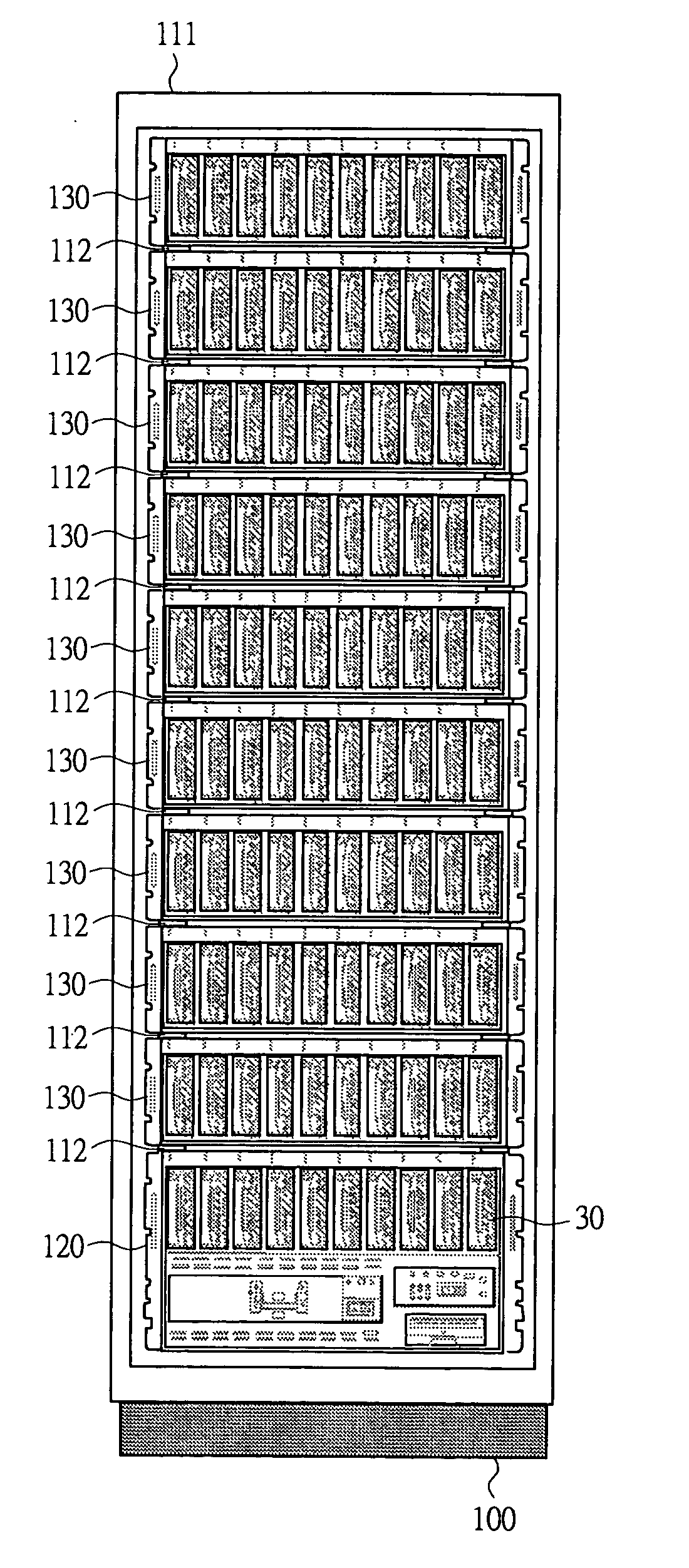
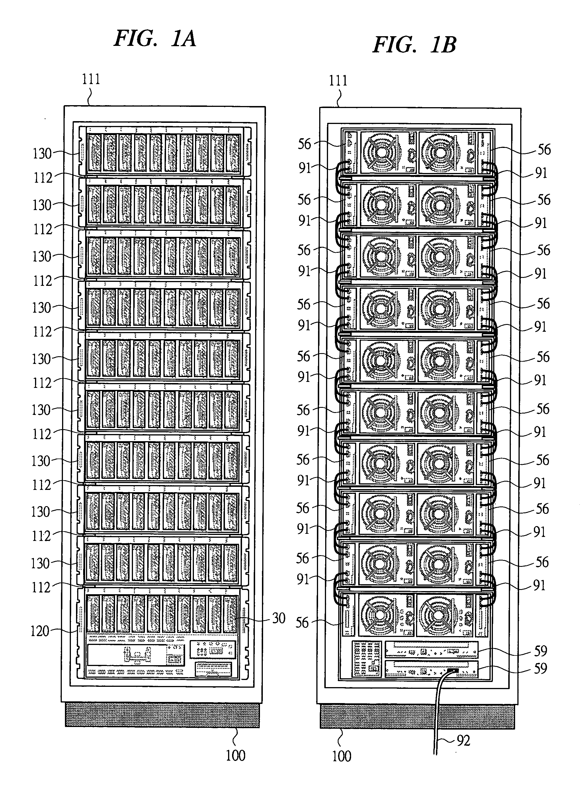
[0049] First, overall configuration of the disk array system of the first embodiment will be described. After that, characteristic processes in the present invention will be described. FIGS. 1A and 1B show external appearance of the hardware configuration of the disk array system according to the first embodiment. FIG. 1A shows a front of the system and FIG. 1B shows the rear thereof. The disk array system 100 has a rack frame 111 as a base and several stages of mount frames 112 arranged vertically inside t...

second embodiment

[0152] Next, a disk array system of the second embodiment of the present invention will be described. According to a backup method of the second embodiment, the process is performed, in which first data and the backup data are stored in a paired volumes, for example, a certain storage volume such as an LU and another storage volume such as another LU so that the storage locations thereof are crossed to each other (hereinafter referred to as cross process) in an overall storage region provided by a plurality of HDDs 30. In other words, the process to arrange a data region and a backup region so that they may cross each other in this pair is performed. Volumes that store the data with different properties, especially, the data with different size are used as the storage volumes to be paired. Hardware configuration or the like is the same as that of the first embodiment.

[0153]FIG. 13 is an explanatory diagram showing an outline of the backup method of the second embodiment. For exampl...

third embodiment

[0166] Next, a disk array system of the third embodiment of the present invention will be described. In a backup method of the third embodiment, a region for storing important data (referred to as important data region) in accordance with an importance level is provided in an overall storage region provided by a plurality of HDDs 30, and the first data to be stored in the HDD 30 is allocated to a region in accordance to is importance level. Also, the data of this first data to be stored in the important data region is automatically backed up as in the case of the first embodiment or the like. The controller 10 backs up only the data in, for example, the important data region. The hardware configuration or the like is the same as that of the first embodiment.

[0167] In comparison to a mainframe-computer system for performing the block access in which stable access unit for data is an LBA, a system such as a network attached storage (NAS) for performing the data access by a path / file ...


PUM


Abstract

The present invention enables to secure data reliability by avoiding data loss in an early failure period of an operation of a disk array system to which no particular measures have been taken conventionally. A controller of the disk array system stores first data to be stored in a HDD into a part of the region of one or more HDDs of an overall storage region composed of a plurality of HDDs and stores backup data of the stored first data into a part of the region of one or more HDDs in such a manner that they may be stored in the different HDDs. When there are no enough free space regions to store the first data in the overall storage region, the region in which the backup data is stored is overwritten to be used.

Description

CROSS-REFERENCE TO RELATED APPLICATION [0001] The present application claims priority from Japanese Patent Application JP 2004-297471 filed on Oct. 12, 2004, the content of which is hereby incorporated by reference into this application. TECHNICAL FIELD OF THE INVENTION [0002] The present invention relates to a disk array system for controlling data storage to a storage device such as a hard disk drive (hereinafter abbreviated as HDD) or the like. More particularly, it relates to a technology for avoiding loss of data stored in a storage region of the disk array system. BACKGROUND OF THE INVENTION [0003] Conventionally, a computer system in which a disk array system is communicably connected to a host information processor such as a host computer of a customer (user) has performed a process to store data from the host to a storage region that the disk array system provides. It has been done particularly in the configuration in which a predetermined RAID system is employed to provide...

Claims


Application Information

Patent Timeline
Patent Type & Authority Applications(United States)
IPC IPC(8): G11C7/10
CPCG06F11/1076G11B27/002G06F2211/1009G06F2211/1014G06F11/1088
Inventor CHIKUSA, TAKASHITAKATA, YUTAKATACHIBANA, TOSHIOMAKI, TAKEHIROHONMA, HIROTAKA
Owner HITACHI LTD
Learn More