
Ink-jet head mount and ink-jet printing apparatus using the same

a technology of inkjet printing and inkjet head, which is applied in the direction of printing, inkjet head, power drive mechanism, etc., can solve the problems of insufficient color filter quality, inability to precisely adjust the nozzle pitch np, pixel pitch pp, and the position of the inkjet head, and increase the number of inferior color filter manufactured

Inactive Publication Date: 2006-04-13
SAMSUNG ELECTRONICS CO LTD
View PDF6 Cites 22 Cited by
  • Summary
  • Abstract
  • Description
  • Claims
  • Application Information

AI Technical Summary

Benefits of technology

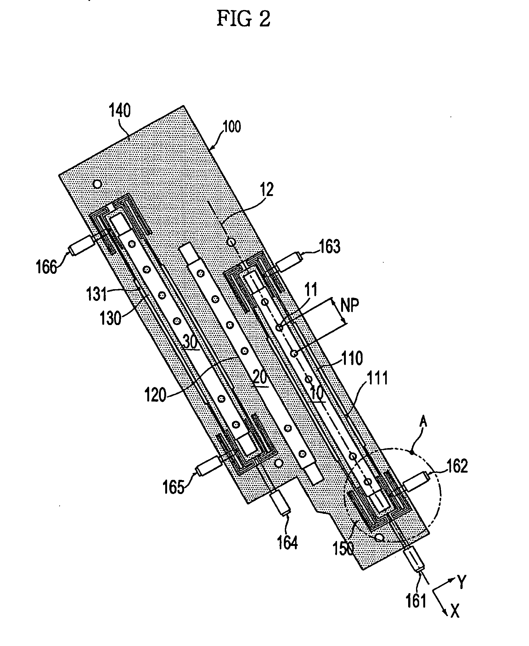
[0013] The present general inventive concept also provides an ink-jet head mount to precisely adjust positions of ink-jet heads by removing driving errors that occur between mechanical components when adjusting the positions of the ink-jet heads and an ink-jet printing apparatus including the same.
[0017] Moreover, the body surrounds the head installer, and the ink-jet head mount can further include a gap to separate the head installer from the body and formed around the head installer so as to secure the minute movement of the head installer.

Problems solved by technology

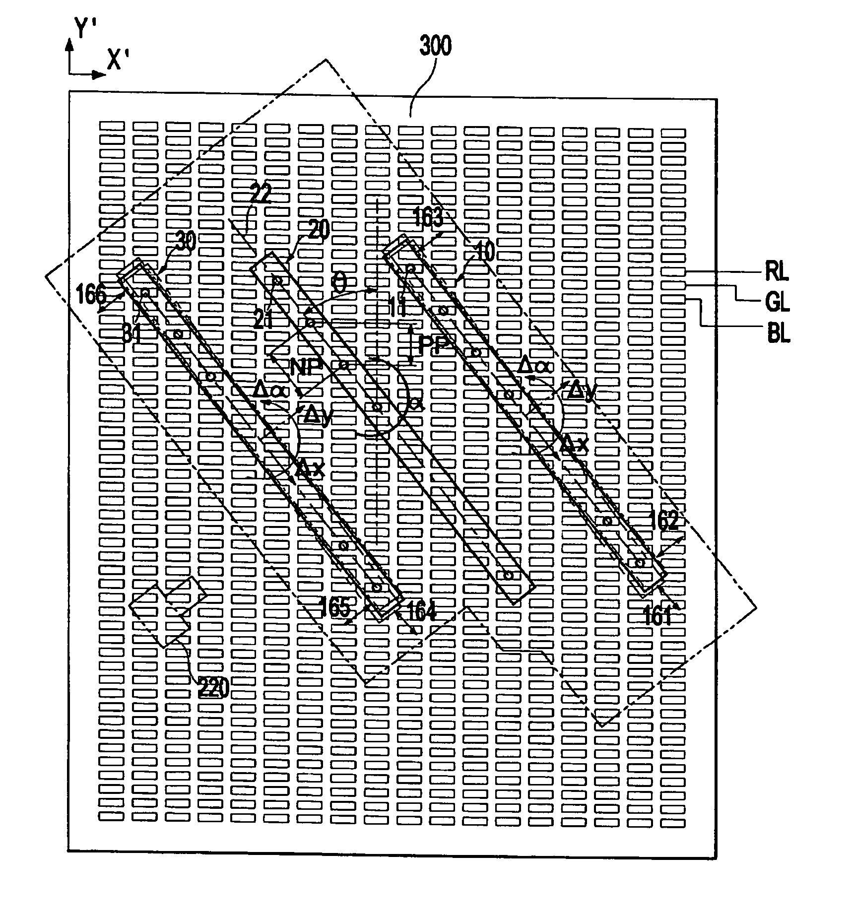
When a high resolution pixel matrix is used (generally, less than a few μm), it is more difficult to precisely adjust the nozzle pitch NP, the pixel pitch PP, and positions of the ink-jet heads.
As a result, ink ejected from the ink-jet heads may not be precisely coated within a desired pixel cavity of the pixel matrix for the color filter and some portion thereof may be coated outside of the desired pixel cavity.
This may lead to an increase in a number of inferior color filters manufactured.
However, the conventional ink-jet heads move according to only two-degrees-of-freedom, so that there is a limit to the precision with which the position of the ink jet heads may be adjusted.
Moreover, since the positions of the conventional ink-jet heads are minutely adjusted by a plurality of mechanical components, driving errors, such as friction between the mechanical components, backlash, pitching, yawing, rolling, or the like, are inevitable, so that the positions of the ink-jet heads cannot be precisely adjusted.

Method used


Image

  • Ink-jet head mount and ink-jet printing apparatus using the same
  • Ink-jet head mount and ink-jet printing apparatus using the same
  • Ink-jet head mount and ink-jet printing apparatus using the same

Examples


Embodiment Construction

[0044] Reference will now be made in detail to the embodiments of the present general inventive concept, examples of which are illustrated in the accompanying drawings, wherein like reference numerals refer to the like elements throughout. The embodiments are described below in order to explain the present general inventive concept while referring to the figures.

[0045] An ink-jet head mount 100 according to an embodiment of the present general inventive concept and an ink-jet printing apparatus including the same will now be described in detail with reference to the accompanying drawings.

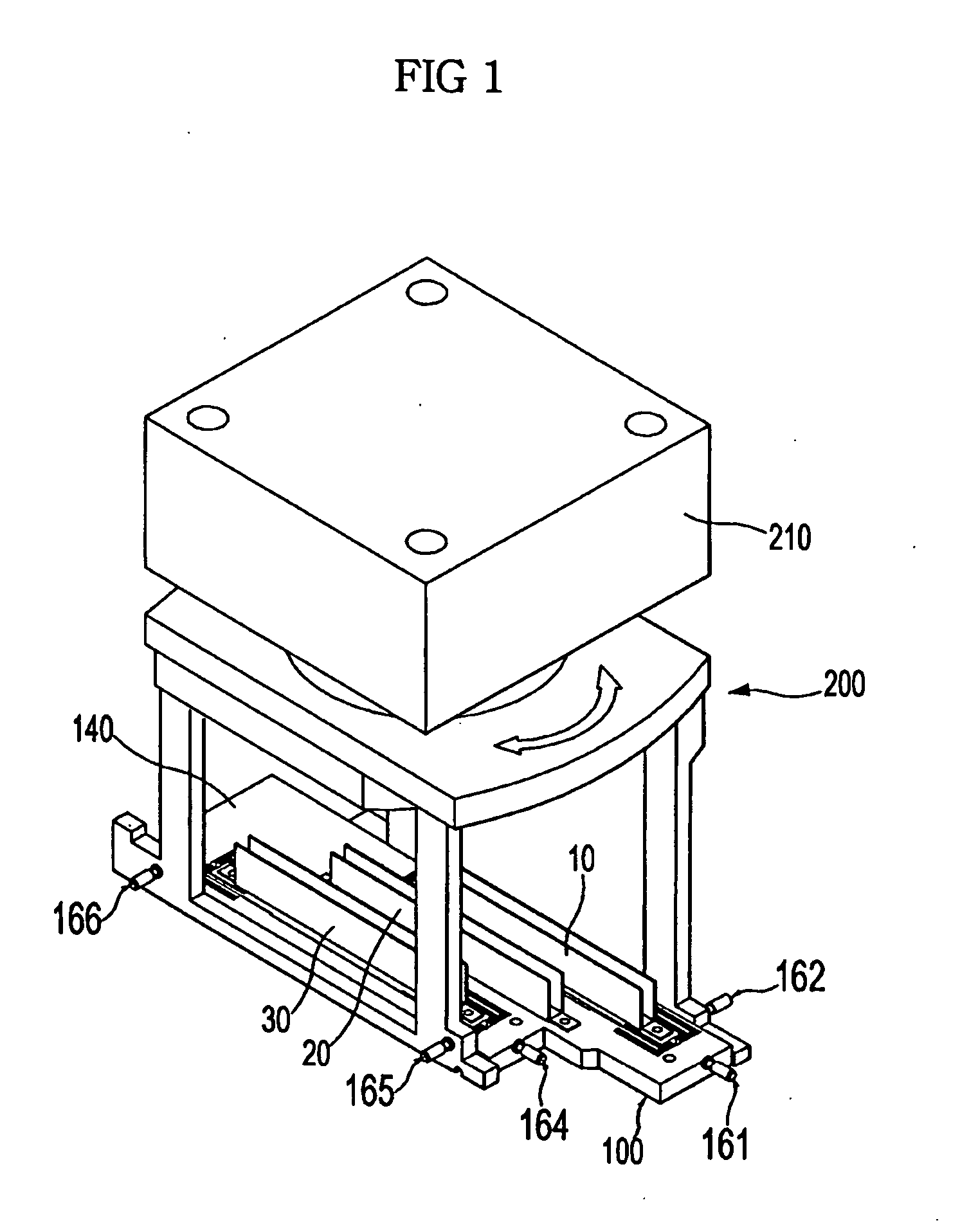
[0046]FIG. 1 is a perspective view illustrating the ink-jet printing apparatus according to an embodiment of the present general inventive concept. As illustrated FIG. 1, the ink-jet printing apparatus includes an R-ink-jet head 10 to eject red (R) colored ink, a G-ink-jet head 20 to eject green (G) colored ink, a B-ink-jet head 30 to eject blue (B) colored ink, the ink-jet head mount 100 in which...


PUM


Abstract

An ink-jet head mount to guide positions of ink-jet heads with a high precision and an ink-jet printing apparatus including the same. The ink-jet printing apparatus includes an ink-jet head having a plurality of nozzles to eject ink, an ink-jet head mount in which the ink-jet head is installed and is movable according to three-degrees-of-freedom, and a frame in which the ink-jet head mount is installed.

Description

CROSS-REFERENCE TO RELATED APPLICATIONS [0001] This application claims the benefit of Korean Patent Application No. 2004-80048, filed on Oct. 7, 2004 in the Korean Intellectual Property Office, the disclosure of which is incorporated herein in its entirety by reference. BACKGROUND OF THE INVENTION [0002] 1. Field of the Invention [0003] The present general inventive concept relates to an ink-jet head mount and an ink-jet printing apparatus using the same, and more particularly to an ink-jet head mount to minutely adjust a position of an ink-jet head to eject red ink, green ink, and blue ink on a glass panel in an ink-jet printing system to manufacture a color filter for a liquid crystal display (LCD). [0004] 2. Description of the Related Art [0005] An ink-jet printing method is used to manufacture a color filter used in thin film transistor-liquid crystal displays (TFT-LCD). A glass panel having a pixel matrix to form the color filter is printed on by a piezo-driven ink-jet head hav...

Claims


Application Information

Patent Timeline
IPC IPC(8): B41J2/15
CPCB41J2/15B41J2202/14B41J2/145B41J2/1752
Inventor SONG, SE KYONGYEOM, KI KEON
Owner SAMSUNG ELECTRONICS CO LTD
Learn More