Plasma display panel comprising bus electrode
- Summary
- Abstract
- Description
- Claims
- Application Information
AI Technical Summary
Benefits of technology
Problems solved by technology
Method used
Image
Examples
first embodiment
A First Embodiment
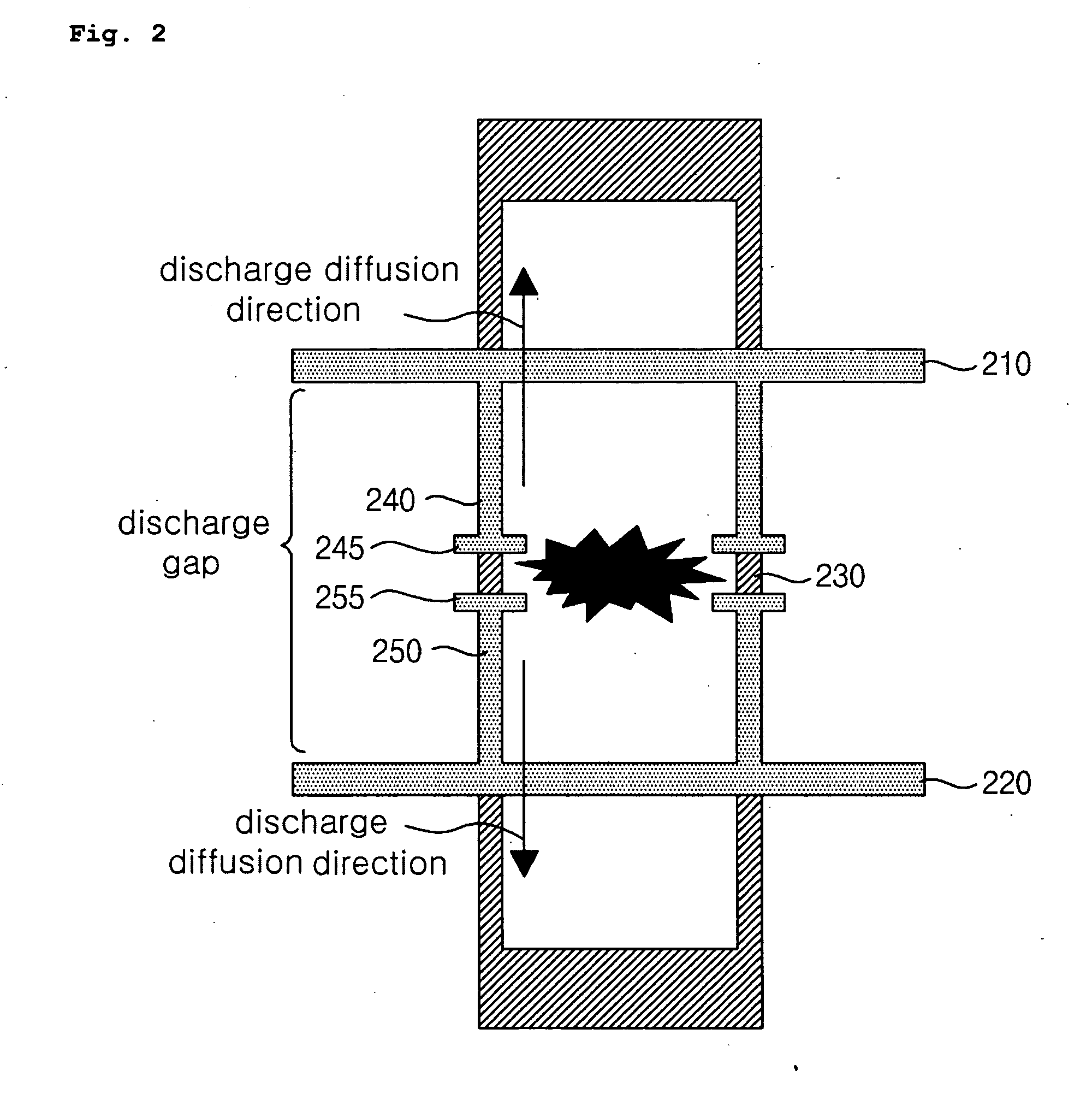
[0046]FIG. 2 is a plan view illustrating a plasma display panel according to a first embodiment of the present invention. As shown in FIG. 2, a plasma display panel according to the first embodiment of the present invention comprises a first bus electrode 210, a second bus electrode 220, a barrier rib 230, a first firing electrode 240 and a second firing electrode 250.
[0047] The first bus electrode 210 and the second bus electrode 220 form a discharge gap 260. The first bus electrode 210 performs the fuction of scan electrode and the second bus electrode 220 performs the sustain electrode fuction.
[0048] The barrier rib 230 forms a discharge cell.
[0049] The first firing electrode 240 is connected to the first bus electrode 210 to protrude in the direction of the center of the discharge cell. The first firing electrode 240 may be formed within a discharge cell. However, preferably, the first firing electrode 240 should be formed on the barrier rib to prevent a dec...
second embodiment
A Second Embodiment
[0054]FIG. 3 is a plan view illustrating a plasma display panel according to a second embodiment of the present invention. As shown in FIG. 3, a plasma display panel according to the second embodiment of the present invention comprises a first bus electrode 310a, 310b and 310c, a second bus electrode 320a, 320b and 320c, a barrier rib 330, a first firing electrode 340 and a second firing electrode 350.
[0055] A plurality of the first bus electrodes 310a, 310b and 310c are disposed in parallel with each other. The ends of the plurality of the first bus electrodes 310a, 310b and 310c are connected to each other. Thus, the plurality of the first bus electrodes 310a, 310b and 310c are not electrically separated, but are electrically connected to perform the scan electrode function.
[0056] A plurality of the second bus electrodes 320a, 320b and 320c are disposed in parallel with each other. The first bus electrode 310a adjacent to the center of discharge cell among the...
third embodiment
A Third Embodiment
[0063] As shown in FIG. 4, a plasma display panel according to the third embodiment of the present invention comprises a first bus electrode 410a, 410b and 410c, a second bus electrode 420a, 420b and 420c, a barrier rib 430, a first firing electrode 440, a second firing electrode 450, a first connection electrode 460 and a second connection electrode 470.
[0064] A plurality of the first bus electrodes 410a, 410b and 410c are disposed in parallel with each other. The plurality of the first bus electrodes 410a, 410b and 410c perform the scan electrode function.
[0065] A plurality of the second bus electrodes 420a, 420b and 420c are disposed on the opposite side of the plurality of the first bus electrodes 410a, 410b and 410c in parallel with each other. The plurality of the second bus electrodes 420a, 420b and 420c perform the ssustain electrode function. The first bus electrode 410a adjacent to the center of discharge cell among the plurality of the first bus electr...
PUM
 Abstract
Description
Claims
Application Information
 - R&D
- Intellectual Property
- Life Sciences
- Materials
- Tech Scout
- Unparalleled Data Quality
- Higher Quality Content
- 60% Fewer Hallucinations
Browse by: Latest US Patents, China's latest patents, Technical Efficacy Thesaurus, Application Domain, Technology Topic, Popular Technical Reports.
© 2025 PatSnap. All rights reserved.Legal|Privacy policy|Modern Slavery Act Transparency Statement|Sitemap|About US| Contact US: help@patsnap.com


