Method and apparatus for separating contaminants in fluids and gas

a technology of fluids and contaminants, applied in water contaminants, water/sludge/sewage treatment, water contaminants, etc., to achieve the effect of promoting the formation of bubbles and promoting the separation of dissolved substances

Inactive Publication Date: 2006-04-06
CODY LINERS
View PDF5 Cites 4 Cited by
  • Summary
  • Abstract
  • Description
  • Claims
  • Application Information

AI Technical Summary

Benefits of technology

[0008] In accordance with the invention, there is provided an apparatus for promoting the separation of dissolved and suspended contaminants from an electrically conductive mixture of water with gas and/or oil, the apparatus comprising: an electrically conductive chamber having an entry end and an exit end for containing the mixture of water with gas and/or oil; a first screen of an electrically conductive metal operatively and electrically connected to the entry end of the chamber for directing the mixture into the chamber; at leas

Problems solved by technology

In addition, many separators inadequately remove suspended particulate matter

Method used


Image

  • Method and apparatus for separating contaminants in fluids and gas
  • Method and apparatus for separating contaminants in fluids and gas
  • Method and apparatus for separating contaminants in fluids and gas

Examples


Embodiment Construction

[0022] Generally, the present invention provides a simple system to augment the separation and filtering process for mixtures of water, oil, and gas.

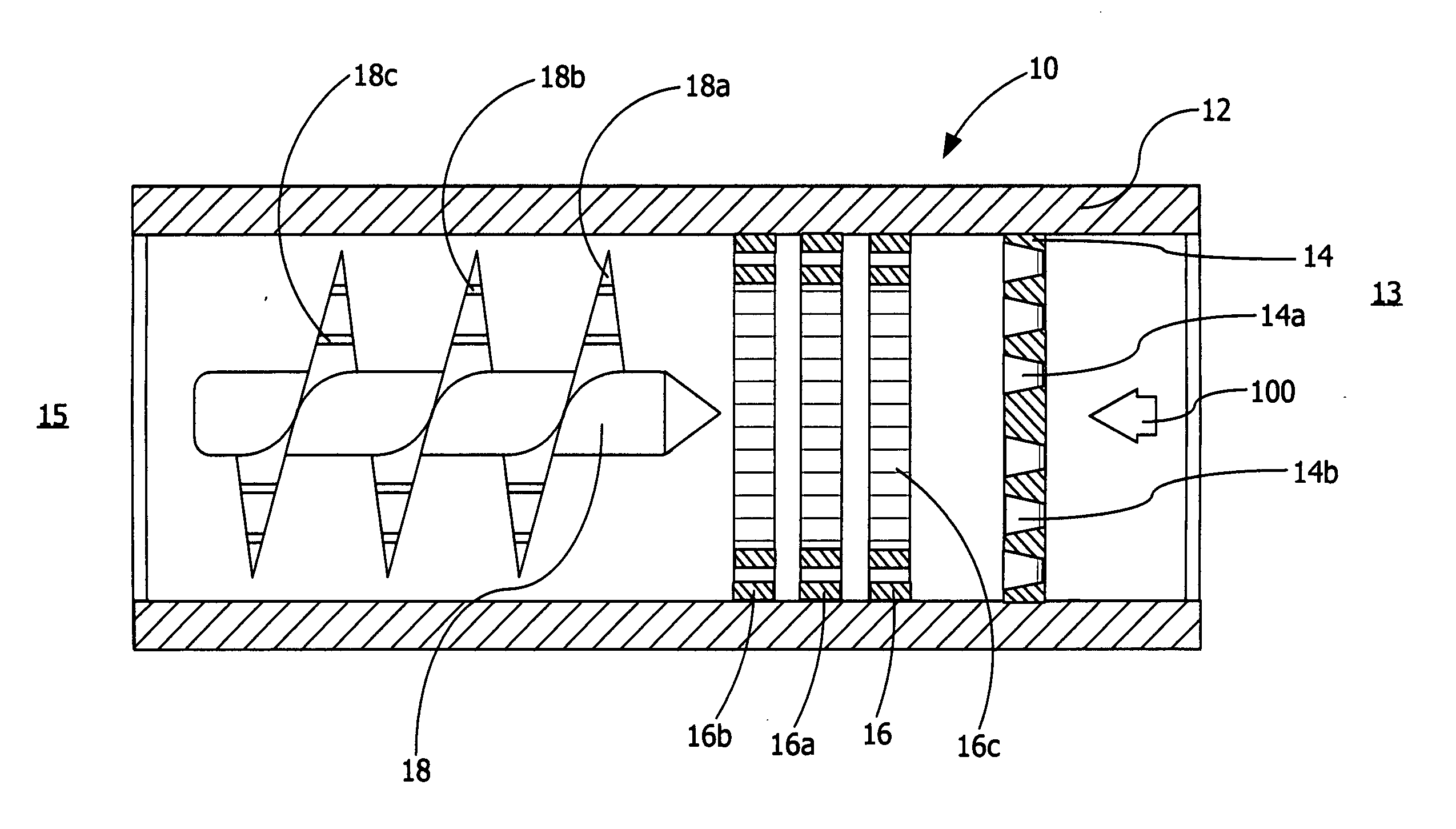
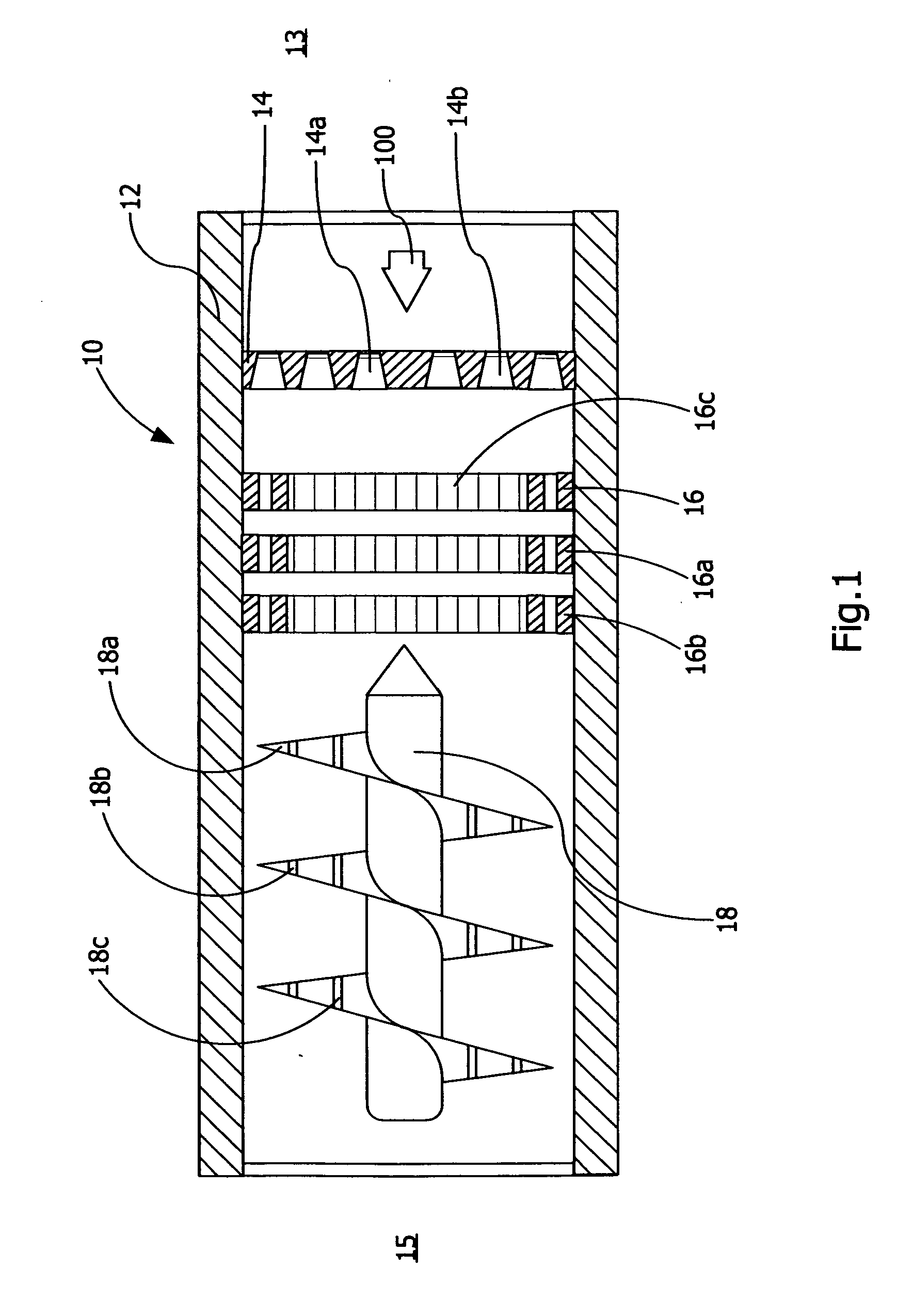
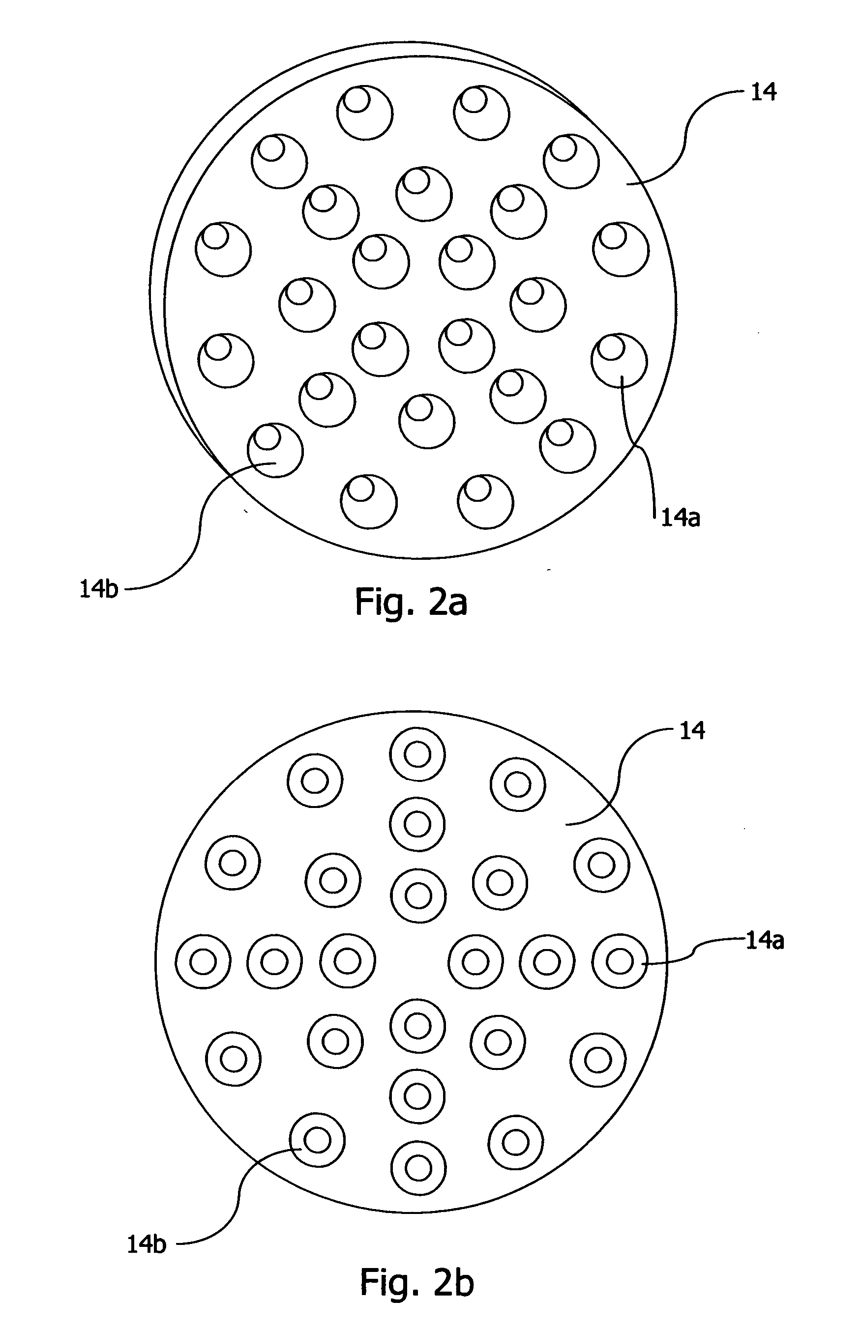
[0023] In FIG. 1 there is illustrated an apparatus to separate contaminants in fluids and gas. A separating apparatus 10 includes a chamber such as a cylindrical tube 12 through which water / oil / gas mixtures may be passed. The apparatus 10 includes an entry plate 14 welded or otherwise attached to the inside of the cylindrical tube 12, at least one wire screen and preferably multiple wire screens 1616a 16b located at suitable intervals downstream of the plate 14 and a helical surface 18 downstream of the screens 1616a 16b. Generally, the plate 14, screens 1616a 16b and perforated helical surface 18 are various combinations of dissimilar metals or metal alloys.

[0024] In operation, a mixture 100 of water with oil and / or gas is introduced under high pressure (typically greater than 50 psi) into the separating apparatus 10 at an upstream e...


PUM

PropertyMeasurementUnit
Timeaaaaaaaaaa
Electrical conductivityaaaaaaaaaa
Sizeaaaaaaaaaa

Abstract

The present invention relates generally to promote separating and filtering contaminants from a mixture of water with oil and/or gas. More particularly, the present invention relates to a method and apparatus for separating contaminants within fluids and gases utilizing a galvanic effect from dissimilar metals within the apparatus.

Description

FIELD OF THE INVENTION [0001] The present invention relates generally to promote separating and filtering contaminants from a mixture of water with oil and / or gas. More particularly, the present invention relates to a method and apparatus for separating contaminants within fluids and gases utilizing a galvanic effect from dissimilar metals within the apparatus. BACKGROUND OF THE INVENTION [0002] As is known, during oil production from producing wells, steam is often injected into wells to reduce the viscosity of oil in the formation and assist in the mobilization of the oil towards the well bore for subsequent pumping to the surface. During the process, the steam condenses to water and is recovered from the well typically as a mixture of water containing dissolved minerals and suspended particulates along with varying amounts of oil and / or gas. [0003] After the mixture of water, oil and gas is pumped to the surface, the mixture is then passed through a separator to separate the wate...

Claims


Application Information

Patent Timeline
IPC IPC(8): C02F1/52
CPCC02F1/46176C02F1/463C02F2101/32C02F2103/10C02F2301/024C02F2301/026
Inventor MCKEARY, LEONARD EUGENE
Owner CODY LINERS
Why Eureka
Try Eureka