Shaft coupling system and method

Inactive Publication Date: 2006-03-30
BALDOR ELECTRIC COMPANY
View PDF21 Cites 6 Cited by
  • Summary
  • Abstract
  • Description
  • Claims
  • Application Information

AI Technical Summary

Benefits of technology

[0003] In general, such systems may transmit power from the prime mover to the driven shaft in a variety of ways. For example, direct couplings may be interposed between the shafts, aligning the shafts axially with one another for direct transmission of rotary motion. Historically, fairly rigid couplings required that the shafts be carefully aligned with one another in order to reduce cyclic loading on both the coupling and the shafts, and on bearing sets supporting the shafts. More modern systems include various types of flexible couplings, generally including elastomeric elements interposed between coupling hardware, which permit some degree of misalignment between the shafts, while effectively transmitting power therebetween. Such flexible couplings also provide some degree of cushioning of torque spikes, and facilitate coupling and uncoupling of the prime mover with the driven shaft.
[0007] Accordingly, there is a need for an improved flexible coupling system which is both extremely rugged and easy to install, even in applications where surrounding obstructions exist or where spacing between driving and driven components is relatively restricted. Similarly, there is a need to lessen the size and number of coupling system components to improve ease of assembly, so to improve ergonomics, reduce assembly / disassembly time, and reduce costs. Further, there is a need for more adaptable systems that more efficiently secure shafts of different sizes. Finally, there is a need to increase torque-carrying capacity to permit downsizing of components, for example, and to meet the ever-increasing demand of more stringent applications. BRIEF DESCRIPTION
[0008] The invention provides an innovative flexible coupling system having a novel securing configuration designed to respond to these needs. For example, a nut or locknut arrangement may be employed in lieu of a typical bolting arrangement to quickly and firmly join a flexible coupling element and the driving and driven shafts. The locknut arrangement compresses and secures the flexible or elastomeric coupling element positioned between mounting structures, such as coupling hub assemblies, that are supported on the shafts. The securing configuration (e.g., a locknut arrangement) is strikingly effective in installation and use, and significantly facilitates assembly and disassembly of the structure. Further, the torque-carrying capacity is notably increased, permitting smaller coupling system components, for example. Moreover, the technique may utilize a novel sleeve / sleeve nut configuration or bushing system to mount structures, such as coupling hub assemblies, to the shafts and other mechanical elements. The sleeve and sleeve nut arrangement significantly improves the ease of securing the hub assemblies to the shafts, as well as, provides for less expensive accommodation of different size shafts. In sum, the present techniques reduce bolting requirements and the numbers of coupling parts, improve ease-of-assembly, increase torque-carrying capacity, and reduce costs and downtime associated with installation and operation of coupling systems and rotating machinery.

Problems solved by technology

While such couplings provide good performance and conveniently permit some degree of misalignment between the driving and driven shafts, they are not without drawbacks.
For example, couplings of the type described above may be somewhat difficult to assemble depending upon surrounding obstructions and on the spacing between the prime mover and the driven machine.
In particular, clearances of the bolts (whether extending axially, radially, or therebetween) may be fairly short where surrounding obstructions are in close proximity or where the machines are placed close to one another.
Such situations make the bolts difficult to insert and tighten into their corresponding threaded bores in the coupling flanges.
In addition, even without obstructions or close spacing, the sheer number of parts (including the bolts, flanges, and other components) in a standard coupling system contribute to the difficulty and time of installing the coupling assembly.
Such complexity increases costs and downtime associated with the installation and operation of couplings systems and rotating machinery.
Further, coupling systems of the type described above often require a significant inventory of relatively expensive mounting structures to accommodate varying shaft sizes.

Method used


Image

  • Shaft coupling system and method
  • Shaft coupling system and method
  • Shaft coupling system and method

Examples


Embodiment Construction

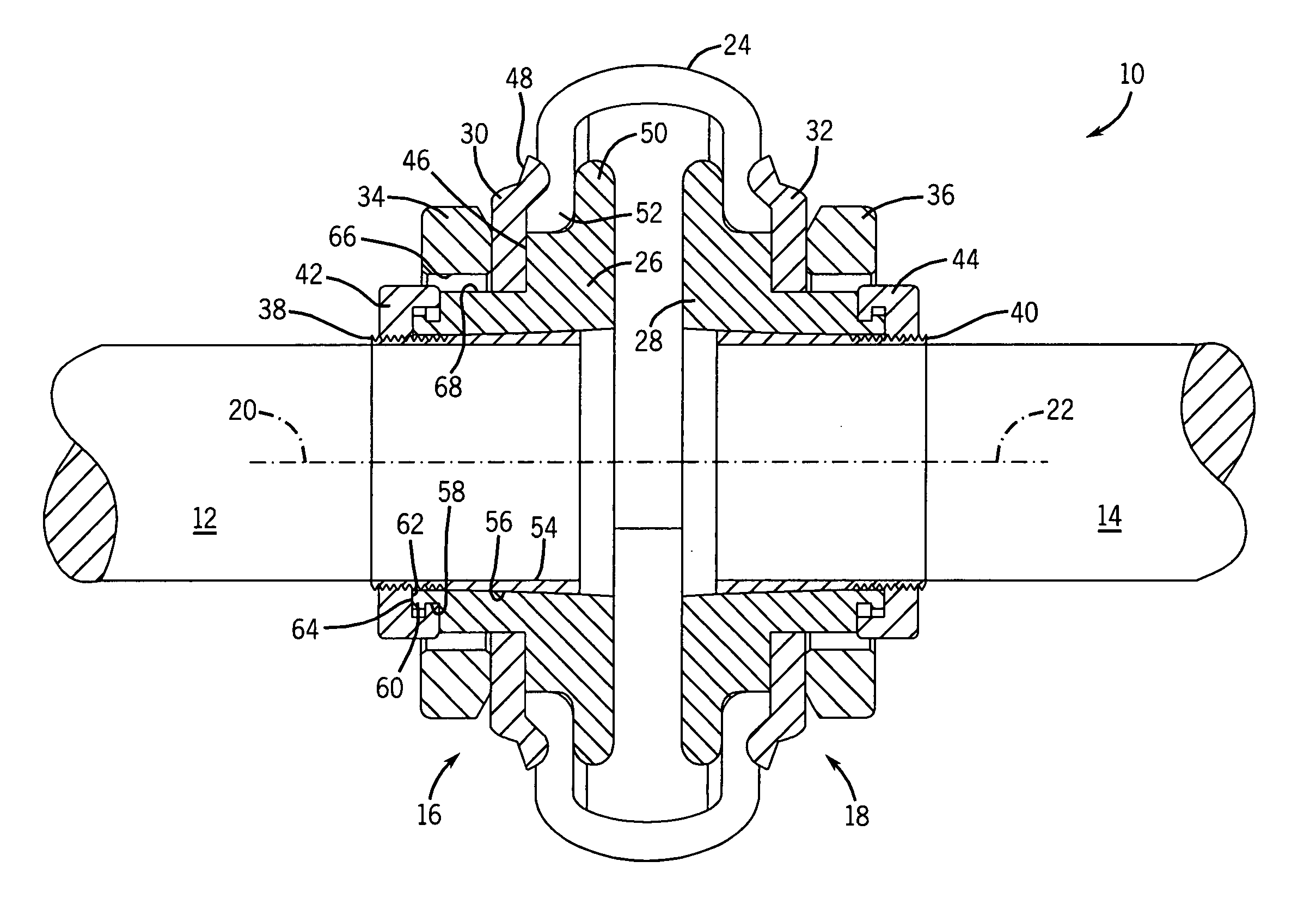
[0020] In general, the present technique provides for the mounting of structures, such as hub assemblies and other hollow members, onto mechanical elements (e.g., shafts) to secure the mechanical elements to one another. For example, FIG. 1 illustrates a coupling system, designated generally by the reference numeral 10, for coupling a first shaft 12 to a second shaft 14. An example of the first shaft 12 is an output shaft from an electric motor, and an example of the second shaft 14 is an input shaft of a driven machine, such as a foot-mounted pump. It should be emphasized that while reference is made to a prime mover in the form of an electric motor and to a driven machine in the form of a pump, the coupling system described herein is not limited to application with any particular type of prime mover or driven machine. In particular, the coupling system can be applied to a wide range of input power sources, such as internal combustion engines, hydraulic motors, jack shafts coupled ...


PUM


Abstract

A coupling assembly having an integral flange hub configured to bear against a flexible coupling element, and an external flange element configured to engage the hub to exert compressive force on the flexible coupling element. The assembly further includes a nut having inner threads configured to mate with a threaded extension of the hub to urge the hub and the external flange element into engagement with the flexible coupling element. The assembly may also include a tapered sleeve and a sleeve nut having inner threads configured to mate with the threaded extension of the tapered sleeve to secure the hub with a shaft.

Description

BACKGROUND [0001] The present invention relates generally to coupling systems for transmitting mechanical power between a motor or other prime mover and a driven machine. More particularly, the invention relates to a flexible coupling system permitting a certain degree of misalignment between driving and driven shafts, which is easy to install and which provides enhanced torque-carrying capacity via an elastomeric element disposed between the shafts. BRIEF DESCRIPTION [0002] A great number of applications exist for rotating machinery including a prime mover or driver coupled to a driven piece of machinery. In many industrial and other applications, such prime movers include electric motors, hydraulic motors, pneumatic motors, internal combustion engines and so forth. These prime movers are commonly used to drive pumps, conveyers, agitators, fans, as well as a great variety of other machines. [0003] In general, such systems may transmit power from the prime mover to the driven shaft ...

Claims


Application Information

Patent Timeline
IPC IPC(8): F16D3/52
CPCF16C35/073F16D3/74F16D1/096F16D2003/745
Inventor NISLEY, DONALD L.
Owner BALDOR ELECTRIC COMPANY
Why Eureka
Try Eureka