Camera

a camera and camera body technology, applied in the field of simple cameras, can solve problems such as failure of photography, and achieve the effect of preventing users

Inactive Publication Date: 2006-03-30
FUJIFILM HLDG CORP +1
View PDF1 Cites 4 Cited by
  • Summary
  • Abstract
  • Description
  • Claims
  • Application Information

AI Technical Summary

Benefits of technology

[0009] A main object of the present invention is to provide a camera capable of preventing a user from photographing in a wrong photography mode.
[0011] Still another object of the present invention is to provide the camera that informs completion of photographing.
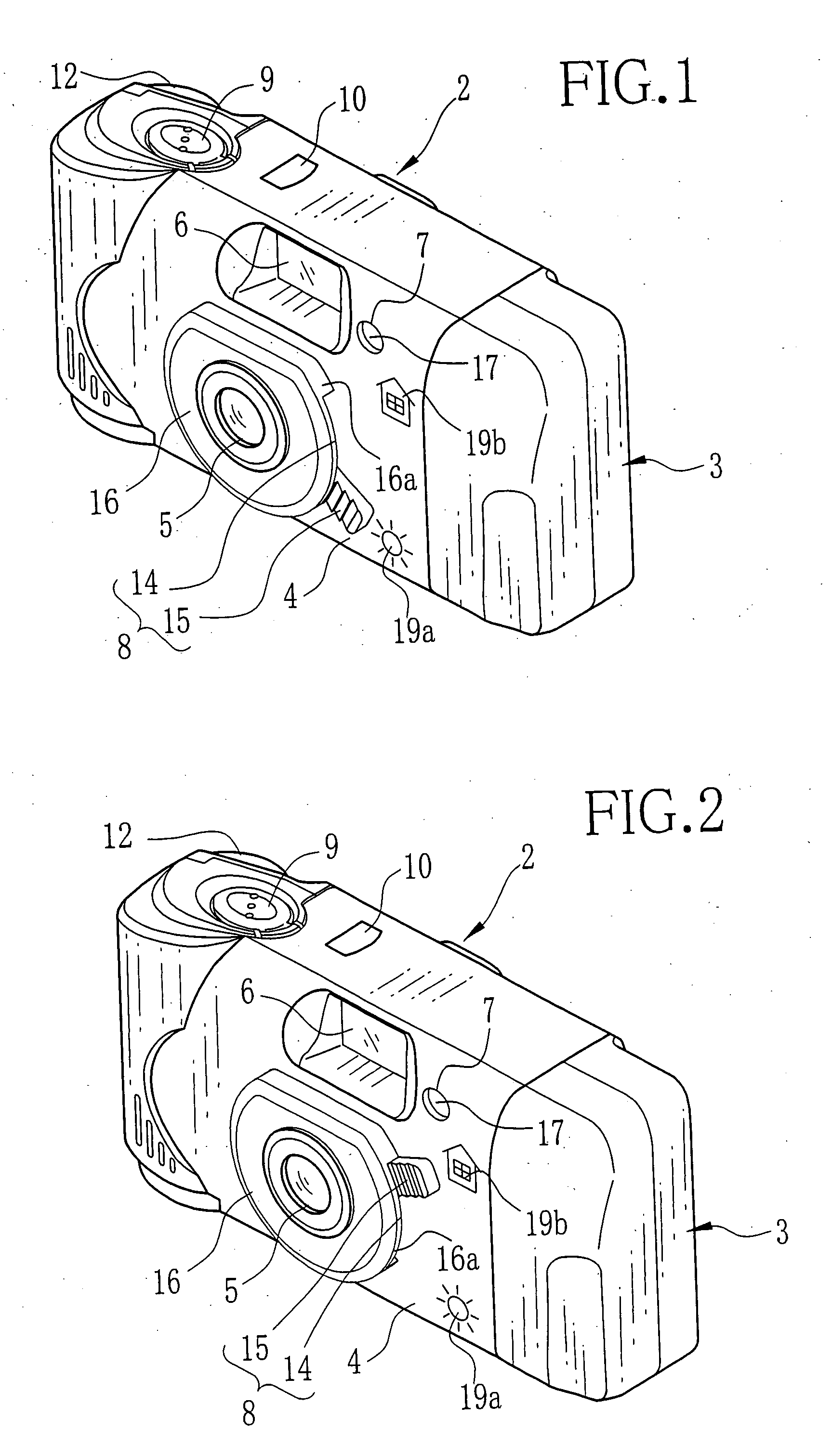
[0014] According to the camera of the present invention, it is possible to prevent a user from photographing in a wrong photography mode, by informing the user of the selected photography mode before photographing by lighting up or blinking the mode indicator when selecting the photography mode. In addition, since the mode indicator blinks on photographing, it is possible for the user to know that the photographing is performed. Furthermore, the user can recognize the selected photography mode, because the mode indicator blinks differently in accordance with the selected photography mode.

Problems solved by technology

However, it is likely for the user to photograph with those lens-fitted photographic film units, without knowing which photography mode is selected.
As a result, such a problem occurs that the user does not notice that the photographing is failed because of a wrong mode selected in photographing.
In addition, in photographing with the lens-fitted photographic film unit having the flash device, although the user can know the selected photography mode when the flash light is emitted, it is likely for the user to photograph without knowing the selected photography mode when a non-flash photography mode is selected.

Method used


Image

  • Camera
  • Camera
  • Camera

Examples


first embodiment

[0084] The light emitting circuit 122 has the same composition as that in the above-stated first embodiment and comprises a condenser 136, a load resistance 137, a power source battery 138, the light emitting element for mode indicator 102, a switch 139, and the sync switch 110. As shown in FIG. 14 to FIG. 16, the switch 139 comprises the contacts 112a and 112b formed on the circuit board 109, and the contact portion 132 formed on the rear surface of the mode selection lever 99. As shown in FIG. 14 or 15, when the mode selection lever 99 is in the first operating position or the second operating position, the switch 139 is in the OFF state because the contact portion 132 does not contact the contacts 112a and 112b. When the mode selection lever 99 moves from the second operating position to the third operating position, the contact portion 132 contacts the contacts 112a and 112b to turn on the light switch 139. The light emitting element for mode indicator 102 blinks when as the syn...

second embodiment

[0092] The stop changeover mechanism and the shutter speed changeover mechanism in the lens-fitted photographic film unit 142 are approximately the same as those in the above first and the

[0093] As shown in FIG. 18A to FIG. 18C, the lens-fitted photographic film unit 142 is provided with mode indicators 148a and 148b for indicating the selected photography mode. Each of the mode indicators 148a and 148b is provided with a light emitting element behind thereof which is turned on / off in accordance with the operation of the mode selection lever 145. As shown in FIG. 18A, when the first photography mode (the daylight photography mode indicated by the indicium 146c) is selected, neither the mode indicators 148a nor 148b emits the light, while the mode indicator 148a alone blinks when the second photography mode (the overcast / evening photography mode) is selected, as shown in FIG. 18B. As shown in FIG. 18C, when the third photography mode (the night view / indoor photography mode) is select...


PUM

PropertyMeasurementUnit
colorsaaaaaaaaaa
speedaaaaaaaaaa
chargeaaaaaaaaaa

Abstract

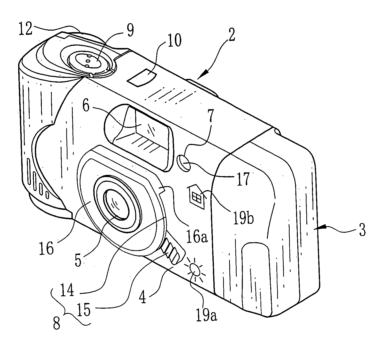
A lens-fitted photographic film unit is provided with a first photography mode and a second photography mode that are for non-flash photographing. In order to photograph in daylight, the first photography mode is selected by operating a mode selection lever. A mode indicator does not operate in the first photography mode. In order to photograph under overcast sky or in a lighted indoor place, the second photography mode is selected by operating the mode selection lever. The mode indicator lights up when the second photography mode is set, and blinks when a release button is depressed to photograph. By lighting and blinking, the mode indicator informs a user of that the second photography mode is selected and photographing has been performed.

Description

BACKGROUND OF THE INVENTION [0001] 1. Field of the Invention [0002] The present invention relates to a simple camera capable of selecting a plurality of photography modes for different exposure settings. [0003] 2. Background Arts [0004] A simple camera having no focusing mechanism or a simplified focusing mechanism has been on the market at a low price. A lens-fitted photographic film unit is also on the market at a low price which has a photographic film preloaded therein at the time of manufacture, and does not require to rewind and remove an exposed photographic film but does only to be handed to a developing laboratory, where the photographic film is developed and photo prints are produced. Some of such a simple camera and a lens-fitted photographic film unit have a flash device incorporated therein for photographing in a dark place such as an indoor place or at nighttime. [0005] There also is a lens-fitted photographic film unit of mode changeover type capable of photographing ...

Claims


Application Information

Patent Timeline
Patent Type & Authority Applications(United States)
IPC IPC(8): G03B17/18G03B7/0805G03B17/04G03C3/00
CPCG03B9/04G03B15/05G03B2219/045G03B2217/002G03B2217/18G03B17/18G03B2215/0503
Inventor MORIYA, MITSUHIRO
Owner FUJIFILM HLDG CORP
Why Eureka
Try Eureka