
Method and system for partitioning the surface of a three dimentional digital object model in order to map a texture

a technology of digital object model and surface, applied in the field of computer graphics, can solve the problems of poor surface representation, difficult to process, and generate methods, and achieve the effect of being easier to process

Active Publication Date: 2006-03-30
WALKER MARK S
View PDF5 Cites 12 Cited by
  • Summary
  • Abstract
  • Description
  • Claims
  • Application Information

AI Technical Summary

Benefits of technology

[0037] Thereby, the texture can be mapped on the digital object model more efficiently and the disadvantages of the prior art are overcome.
[0041] The memory comprising texture data is more efficiently used in interactive applications;
[0042] Since the number of partitions is small (in the order of the number of the original scans), these partitions are easier to process.

Problems solved by technology

This method generates a lot of problems.
Building a mesh where each region is sampled by points from only one scan, results in a poor representation of the surface.
Difficulties also arise when the method is applied to scans divided into two or more separate meshes.
However, the computation of the texture is not optimised.
Furthermore, the texture is not human readable, or is not suitable for mipmapping.
However, the texture is not human readable, and flattening on its own does not guarantee that the resulting texture will be compact enough for packing into a square texture image.
This can result in a large number of patches for an object with many small features.
The problem is that the computation of the texture is inefficient with irregular patches that don't pack well.
By shattering the texture into many small patches, the human readability can also be very poor.
Methods according to the prior art, produce a texture that is not human readable and not suitable for mipmapping.
Furthermore, the computation of the texture is not optimised.
Patches are irregular and don't pack well.
It results in a waste of memory for storing texture data.

Method used


Image

  • Method and system for partitioning the surface of a three dimentional digital object model in order to map a texture
  • Method and system for partitioning the surface of a three dimentional digital object model in order to map a texture
  • Method and system for partitioning the surface of a three dimentional digital object model in order to map a texture

Examples


Embodiment Construction

[0052] The following description is presented to enable one or ordinary skill in the art to make and use the invention and is provided in the context of a patent application and its requirements. Various modifications to the preferred embodiment and the generic principles and features described herein will be readily apparent to those skilled in the art. Thus, the present invention is not intended to be limited to the embodiment shown but is to be accorded the widest scope consistent with the principles and features described herein.

Method for Partitioning a 3D Surface in Order to Map a Texture

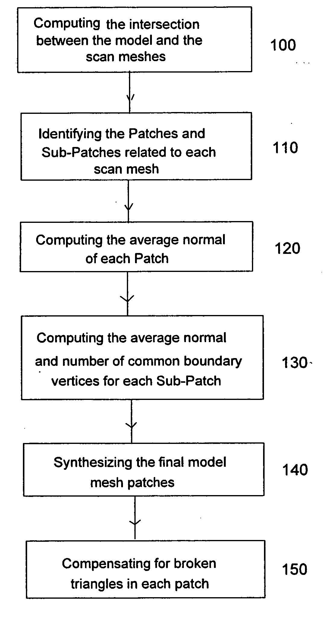
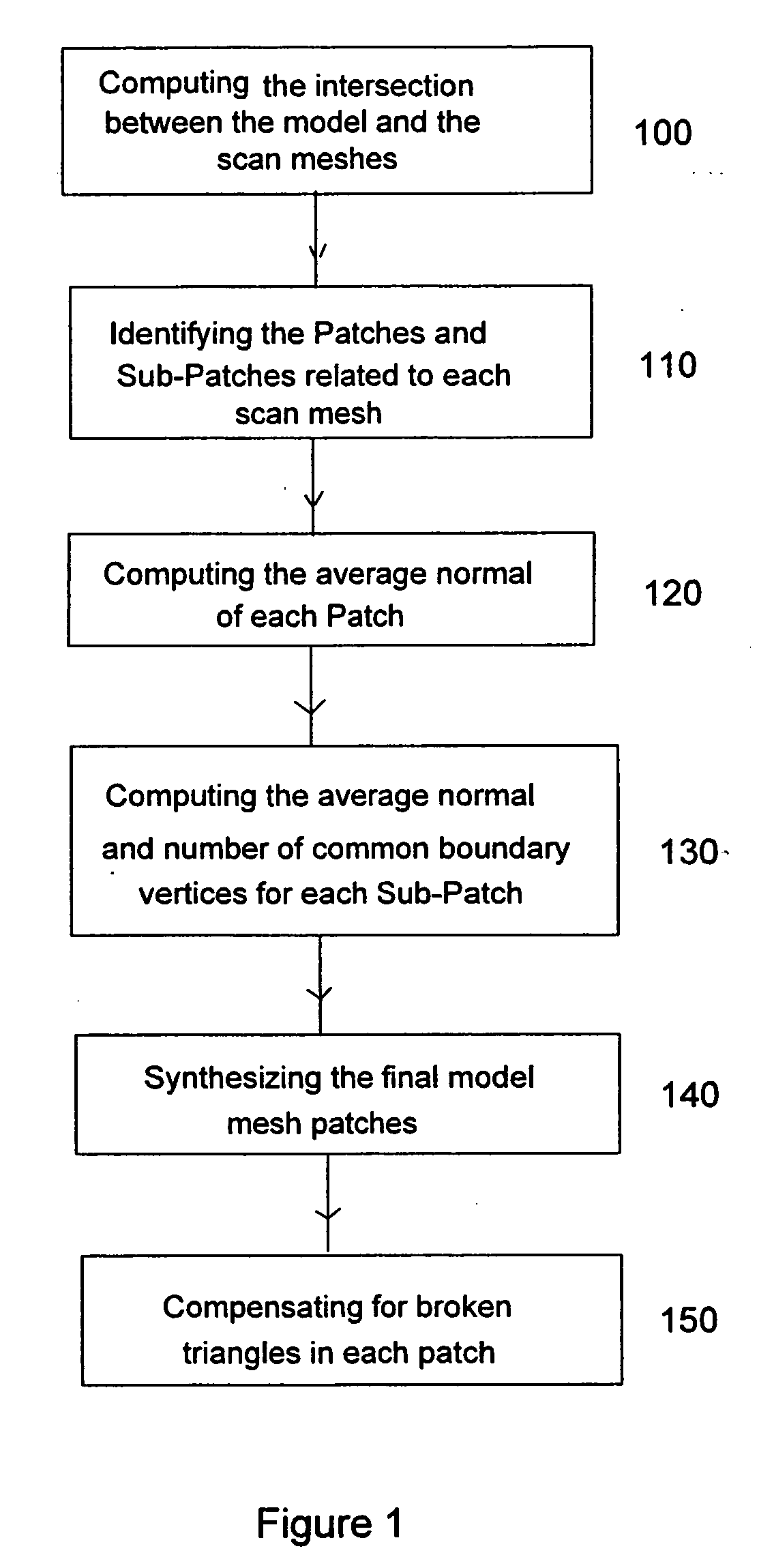
[0053] Reference is made to FIG. 1, which is a logic flow diagram showing the main steps of the method for partitioning a three dimensional (3D) surface in order to map a texture according to the present invention.

[0054] The present method is heuristic and uses the original captured scan information. After the alignment of the scans, the method divides the digital model triangle mesh, wher...


PUM


Abstract

The present invention is directed to a method and system and computer program for decomposing a triangle mesh representing the surface of a digital object model, reconstructed from 3D scanning data, into a small number of height-field patches (partitions) (in the order of the number of the original scans) with reasonable angular variations with the direction from which the viewer is looking at the digital object and with boundaries as regular as possible, in order to map a texture. The present method uses the original scan information (even when scans are divided into two or more connected meshes), but without selecting a single scan per mesh area.

Description

TECHNICAL FIELD OF THE INVENTION [0001] The present invention relates to the field of computer graphics, to a method and system for efficiently partitioning the surface of a three dimensional (3D) digital object model, reconstructed from scanning data, to map a texture. BACKGROUND ART Technical Field [0002] The creation of three dimensional digital objects by scanning real objects has become a common practice in computer graphics applications, such as computer games, electronic commerce, virtual museums. A variety of techniques are used to capture a digital model from a physical object. Laser triangulation systems (for objects smaller than a meter in the largest dimension) are good examples of popular devices for capturing range images (a scan image wherein each pixel in the image represents a three dimensional point). The creation of a digital model from a series of captured scans comprises the following steps. After removal of disconnected points not related to the scanned object,...

Claims


Application Information

Patent Timeline
Patent Type & Authority Applications(United States)
IPC IPC(8): G06T17/20G06T15/30
CPCG06T17/20
Inventor ELSHISHINY, HISHAM EMAD EL-DIN
Owner WALKER MARK S
Learn More