
Liquid crystal display device

Active Publication Date: 2006-03-23
PANASONIC LIQUID CRYSTAL DISPLAY CO LTD +1
View PDF8 Cites 26 Cited by
  • Summary
  • Abstract
  • Description
  • Claims
  • Application Information

AI Technical Summary

Benefits of technology

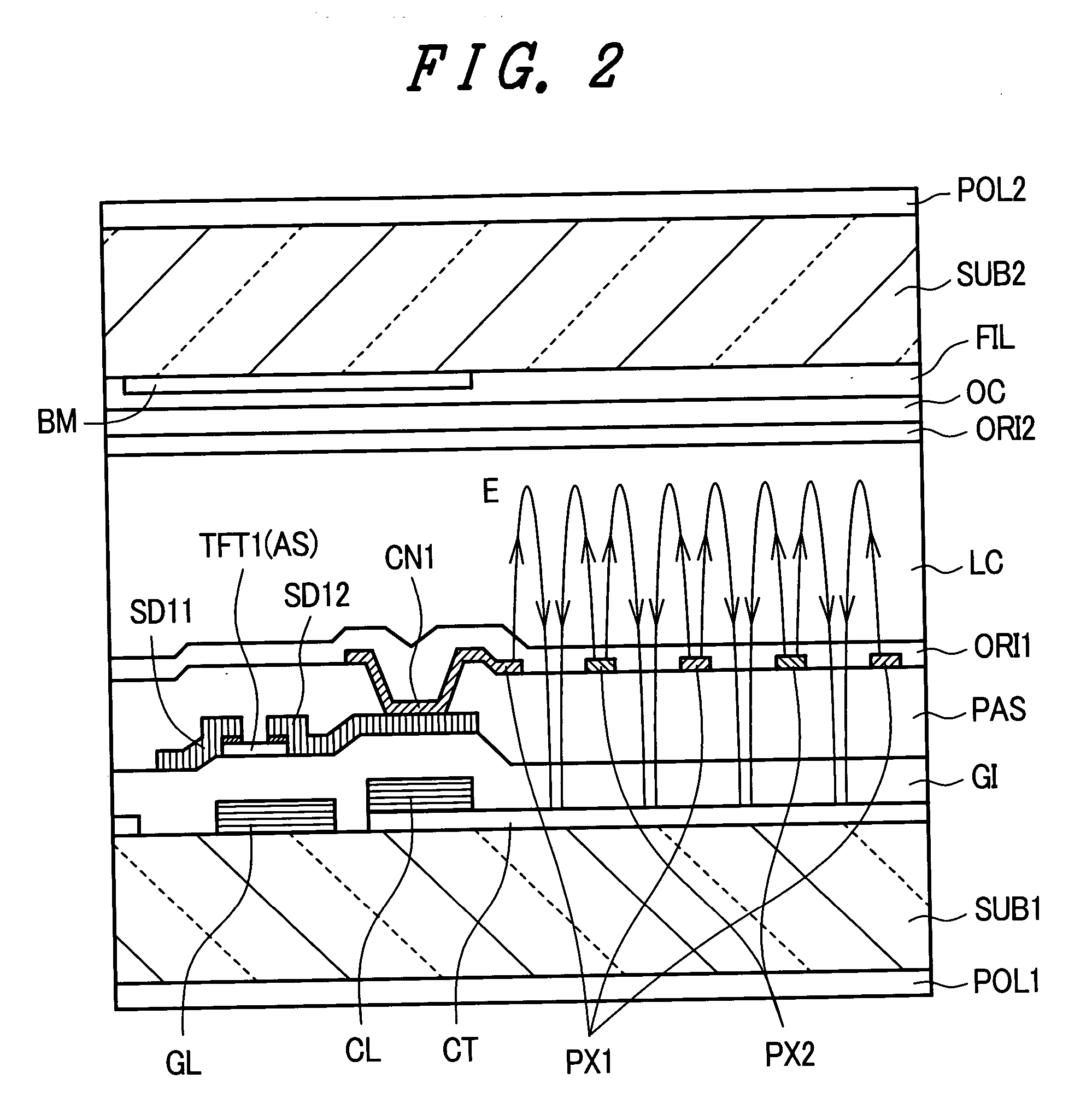
[0014] The present invention has been made under such circumstances and it is one advantage of the present invention to provide a liquid crystal display device which can prevent the brightness in a pixel from being halved even when short-circuiting arises between a pixel electrode and a counter electrode.
[0015] To briefly explain the summary of typical inventions among the inventions disclosed in this specification, they are as follows. (1)
[0016] A liquid crystal display device according to the present invention includes, for example, a pixel electrode and a counter electrode in a pixel formed on a surface of a substrate which faces liquid crystal, the counter electrode is formed below an insulation film, and the pixel electrode is formed above the insulation film, wherein
[0017] the pixel electrode is constituted of separate pixel electrodes which are formed on the counter electrode in an overlapped manner to which a video signal which is supplied to the pixel is inputted to the separate pixel electrodes through separate switching elements at the same timing, and the separate pixel electrodes are respectively formed of a plurality of electrodes and the respective electrodes are alternately arranged. (2)
[0018] A liquid crystal display device according to the present invention is, for example, on the premise of the constitution (1), characterized in that the separate switching elements are turned on in response to a signal from a common gate signal line. (3)
[0019] A liquid crystal display device according to the present invention is, for example, on the premise of the constitution (1), characterized in that one pixel electrode out of the separate pixel electrode has a comb-teeth-shaped pattern in which a conductive body to which respective electrodes are commonly connected is arranged close to one of drain signal lines which are arranged to sandwich the pixels, and another pixel electrode out of the separate pixel electrode has a comb-teeth-shaped pattern in which a conductive body to which respective electrodes are commonly connected is arranged close to another drain signal line. (4)

Problems solved by technology

Further, in such a constitution, when short-circuiting arises between the pixel electrode and the counter electrode which is arranged below the pixel electrode by way of an insulation film through a pin hole, a so-called point defect arises.

Method used


Image

  • Liquid crystal display device
  • Liquid crystal display device
  • Liquid crystal display device

Examples


Embodiment Construction

[0049] Hereinafter, an embodiment of a liquid crystal display device according to the present invention is explained in conjunction with drawings.

[0050]FIG. 8 is an equivalent circuit diagram showing one embodiment of the liquid crystal display device according to the present invention. The equivalent circuit shown in FIG. 8 is an equivalent circuit which is formed on a liquid-crystal-side surface of one substrate out of respective substrates which are arranged to face each other with liquid crystal therebetween.

[0051] First of all, on the above-mentioned substrate surface, gate signal lines GL which extend in the x direction and are arranged in parallel in the y direction are formed and, at the same time, drain signal lines DL which extend in the y direction and are arranged in parallel in the x direction are formed. A portion surrounded by the gate signal lines GL and the drain signal lines DL forms a pixel region where a pixel is formed, and a liquid crystal display part AR is ...


PUM

PropertyMeasurementUnit
widthaaaaaaaaaa
conductiveaaaaaaaaaa
electric fieldaaaaaaaaaa

Abstract

The present invention provides a liquid crystal display device which includes a pixel electrode and a counter electrode in a pixel formed on a surface of a substrate which faces liquid crystal, the counter electrode is formed below an insulation film, and the pixel electrode is formed above the insulation film, wherein the counter electrode is formed over a whole area of a center except for a slight periphery of at least the pixel, the pixel electrode is constituted of separate pixel electrodes to which a video signal which is supplied to the pixel is inputted through the separate switching elements at the same timing, and the separate pixel electrodes are respectively formed of a plurality of electrodes and the respective electrodes are alternately arranged.

Description

BACKGROUND OF THE INVENTION [0001] 1. Field of the Invention [0002] The present invention relates to a liquid crystal display device, and more particularly to a liquid crystal display device which forms pixel electrodes and counter electrodes on a liquid crystal surface side of one substrate out of respective substrates which are arranged to face each other with liquid crystal therebetween. [0003] 2. Description of the Related Art [0004] This type of liquid crystal display device is configured to control a quantity of light which passes through a region defined between pixel electrodes and counter electrodes by driving liquid crystal to which an electric field generated between respective electrodes is applied. [0005] Such a liquid crystal display device has been known as a display device which exhibits excellent property in a so-called wide viewing angle, wherein the display is not changed even when viewed from the oblique direction with respect to a display surface. [0006] Heretof...

Claims


Application Information

Patent Timeline
Patent Type & Authority Applications(United States)
IPC IPC(8): G02F1/1343
CPCG02F1/134363G02F2201/508G02F1/13624
Inventor MORI, IKUKOONO, KIKUO
Owner PANASONIC LIQUID CRYSTAL DISPLAY CO LTD
Learn More