
Device and method for detecting anomolies in a wire and related sensing methods

a technology of anomoly and sensing method, which is applied in the field of detection and localization of anomalies on cables and wires, can solve the problems of more harm, damage that is trying to be avoided, and difficulty in detecting many of the above-described anomalies with visual inspections

Active Publication Date: 2006-03-23
UNIV OF UTAH RES FOUND
View PDF17 Cites 74 Cited by
  • Summary
  • Abstract
  • Description
  • Claims
  • Application Information

AI Technical Summary

Benefits of technology

[0008] In a preferred embodiment, the present invention is a handheld device having a timer circuit for testing integrity of a wire, wherein a circuit is taught that enables determination ...

Problems solved by technology

Unfortunately, testing wires can actually cause more harm if the wires must be removed for inspection.
Even if the wires are functioning properly upon inspection, reinsertion of the wires into the body of the aircraft can result in the damage that is trying to be avoided.
Furthermore, detecting many of the above-described anomalies is difficult to accomplish with visual inspections.

Method used


Image

  • Device and method for detecting anomolies in a wire and related sensing methods
  • Device and method for detecting anomolies in a wire and related sensing methods
  • Device and method for detecting anomolies in a wire and related sensing methods

Examples


Embodiment Construction

[0053] Reference will now be made to the exemplary embodiments illustrated in the drawings, and specific language will be used herein to describe the same. It will nevertheless be understood that no limitation of the scope of the invention is thereby intended. Alterations and further modifications of the inventive features illustrated herein, and additional applications of the principles of the inventions as illustrated herein, which would occur to one skilled in the relevant art and having possession of this disclosure, are to be considered within the scope of the invention.

[0054] Before describing the presently preferred embodiment of the invention, it is useful to have some sort of context in order to understand how the various embodiments that are disclosed in this application are applicable to the rather narrowly focused title of the invention. The present invention includes several techniques for determining wire characteristics. The first broad technique utilizes what is ref...


PUM


Abstract

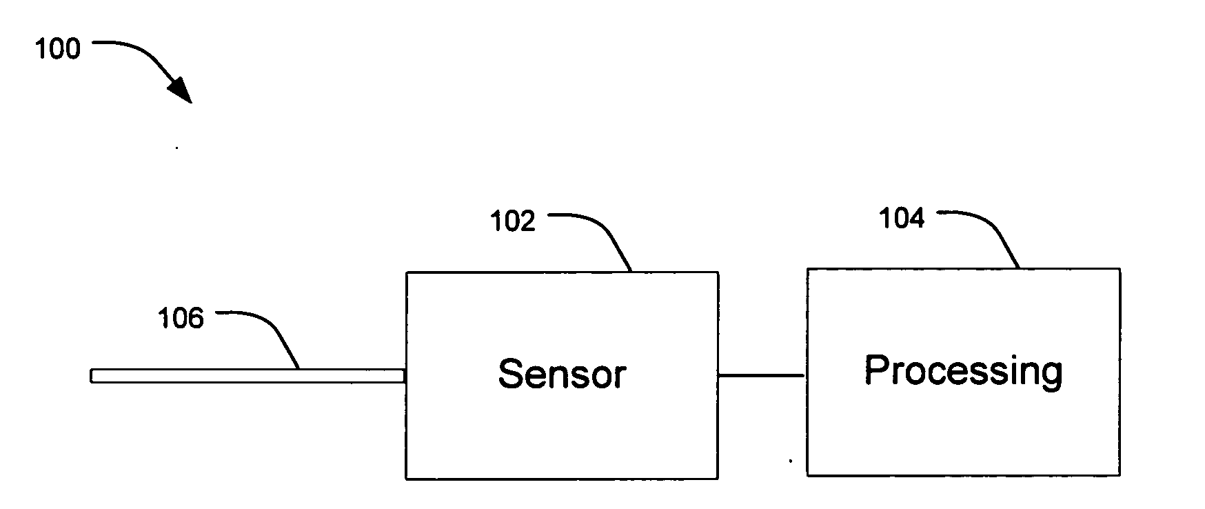
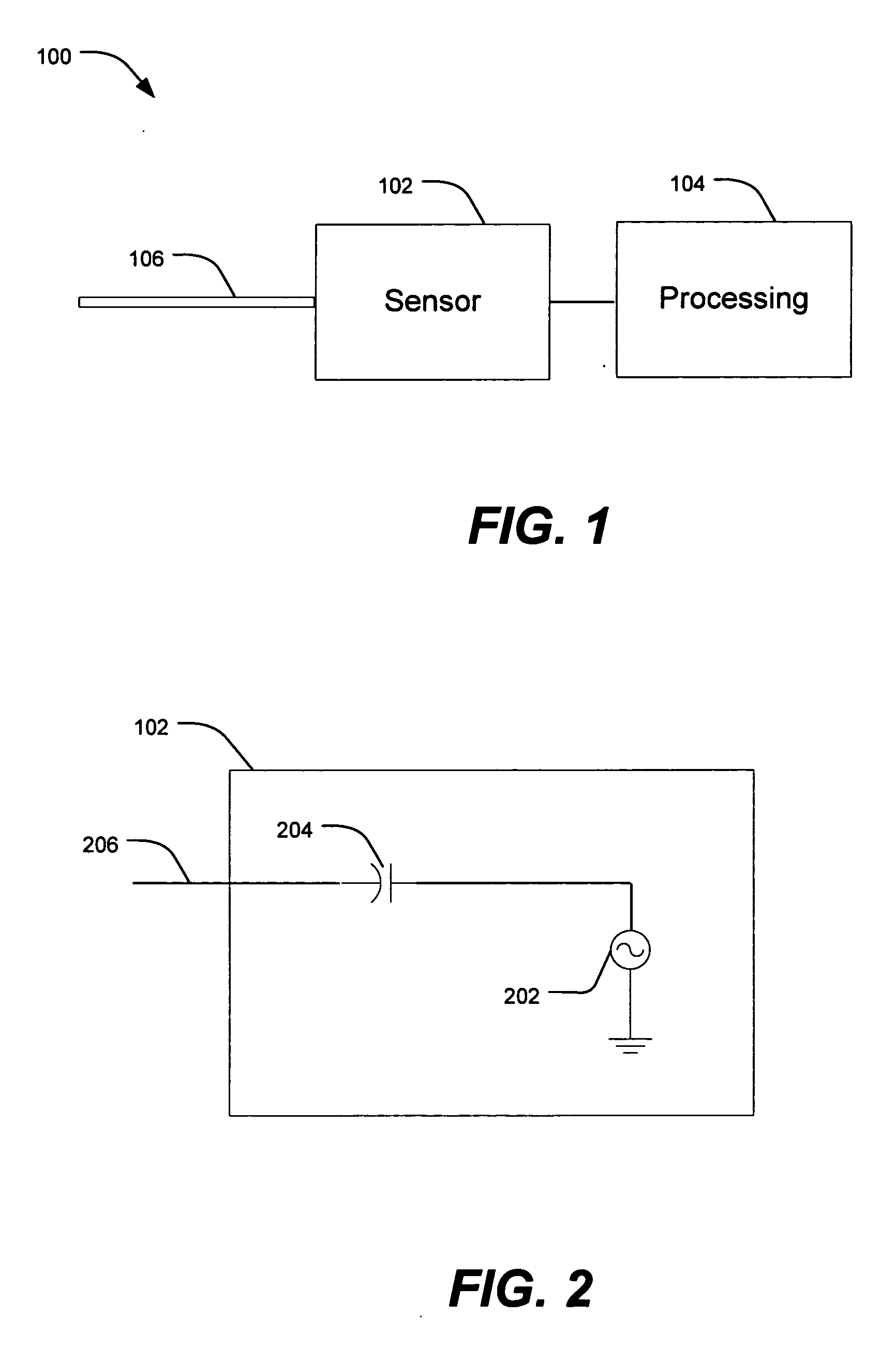
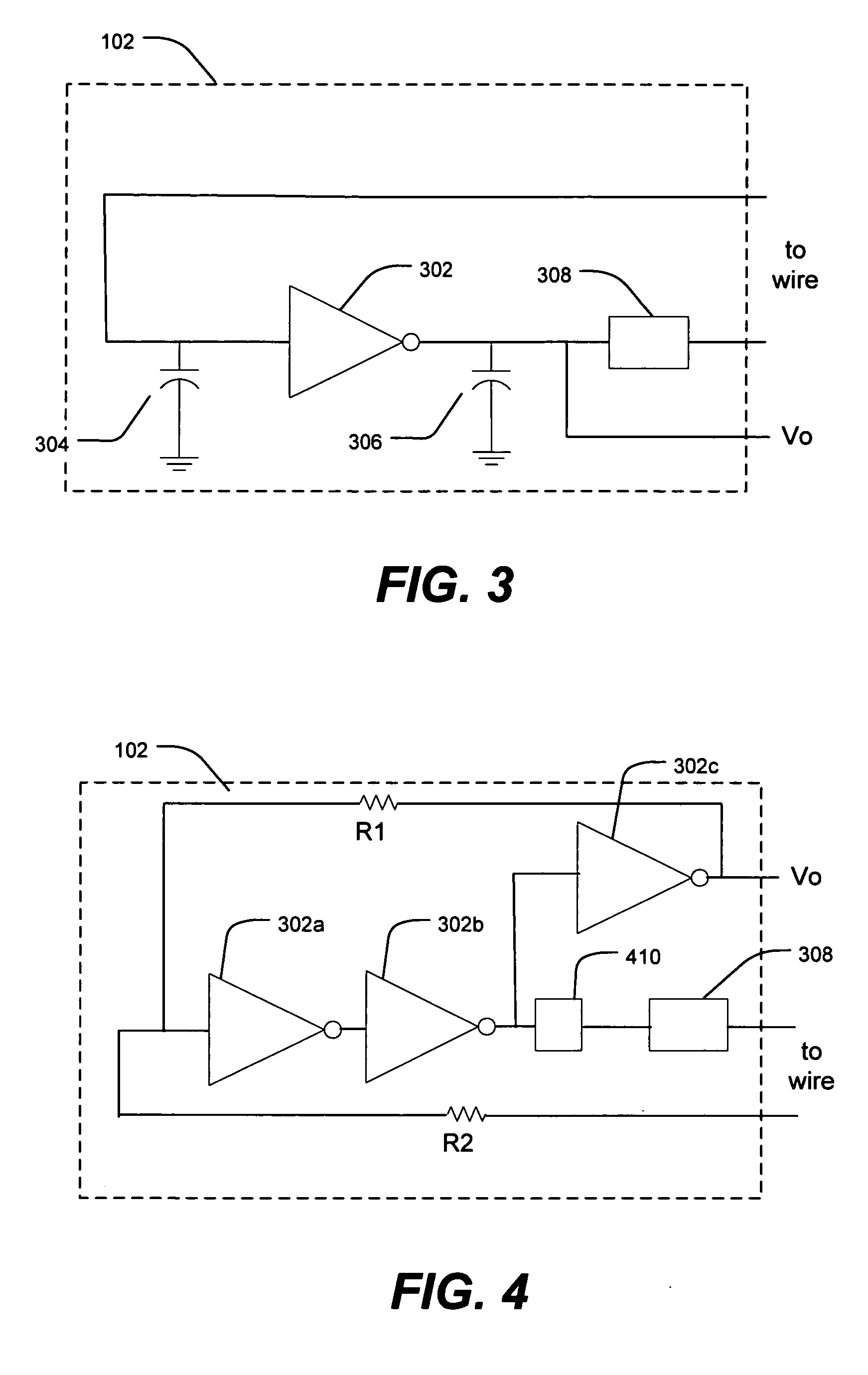
A device and method for measuring the electrical properties of electronic signal paths, including wires and wireless channels. The device may be used for detecting open circuits, short circuits, and the lengths of wires.

Description

CROSS-REFERENCE TO RELATED APPLICATIONS AND CLAIM OF PRIORITY [0001] This application is a continuation-in-part of copending PCT Application No. PCT / US03 / 37233 filed on 19 Nov. 2003 entitled “Device and Method for Detecting Anomolies in a Wire and Related Sending Methods,” which claims the benefit of U.S. application Ser. No. 60 / 427,737 filed on 19 Nov. 2002 entitled “Handheld Device for Detecting Open, Short and Location of Anomaly on a Wire,” U.S. application Ser. No. 60 / 455,788 filed on 18 Mar. 2003 entitled Noise Domain Reflectometer Apparatus and Method for Determining the Integrity and / or Lengths of Signal Paths,” U.S. application Ser. No. 60 / 459,482 filed on 31 Mar. 2003 entitled “Mixed Signal Reflectometer Apparatus and Method for Determining the Integrity of Signal Paths,” and U.S. application Ser. No. 60 / 477,391 filed on 9 Jun. 2003 entitled “Method and System for Robust Multi-Carrier Spread Spectrum Data Transmission over Partially Jammed Channels.” All of the above appli...

Claims


Application Information

Patent Timeline
IPC IPC(8): G01R31/08G01DG01J1/04G01J1/42G01J5/08G01R31/02G01R31/11G01R31/302H01T13/60H03H7/30H03H7/40H03H11/12H03K5/159H04W24/00
CPCG01R31/11H04W24/00H03H11/126
Inventor FURSE, CYNTHIAMAHONEY, JOHNCHUNG, YOU CHUNGAMARNATH, NIRMAL NATH
Owner UNIV OF UTAH RES FOUND
Learn More