
System and method for using magnetic sensors to track the position of an object

a technology of magnetic sensors and objects, applied in the field of systems and methods for tracking the position of objects, can solve the problems of ultrasound failure on a small scale, the distance between the transmitter and any object within the volume may be too small to measure a time-delay, and the above-described position detection system is currently impractical or unworkabl

Inactive Publication Date: 2006-03-23
WALLANCE DANIEL I +2
View PDF39 Cites 42 Cited by
  • Summary
  • Abstract
  • Description
  • Claims
  • Application Information

AI Technical Summary

Benefits of technology

[0007] Embodiments of the invention are directed to a wireless and real-time small-scale position tracking device, which may be used, for example, to construct and operate a three-dimensional computer mouse. A t...

Problems solved by technology

At even smaller distances, such as for a volume of several cubic feet or less, the above-described position detection systems become currently impractical or unworkable.
If a radio-frequency transmitter were mounted within such a volume, the distance between the transmitter and any object within the volume may be too small to measure a time-delay with the precision needed for position tracking in most applications.
Ultrasound also fails on a small scale, for reasons similar to those described above.
Various optical techniques exist to wirelessly track position within a small volume, for example, by using multiple infrared lasers; however, these systems require the target object to remain in constant view of the tracking system, thus limiting the systems' usefulness.

Method used


Image

  • System and method for using magnetic sensors to track the position of an object
  • System and method for using magnetic sensors to track the position of an object
  • System and method for using magnetic sensors to track the position of an object

Examples


Embodiment Construction

[0021] Embodiments of the invention are directed to a wireless and real-time small-scale position tracking device, which may be used, for example, to construct and operate a three-dimensional computer mouse. A standard computer mouse is limited to two-dimensional movement. A three-dimensional computer mouse containing, for example, a small magnet, may be operated within a defined three-dimensional volume to allow the position of the mouse to be determined at all times. Such a three-dimensional computer mouse may be used in applications ranging from 3D computer aided design (CAD) development, to 3D computer gaming.

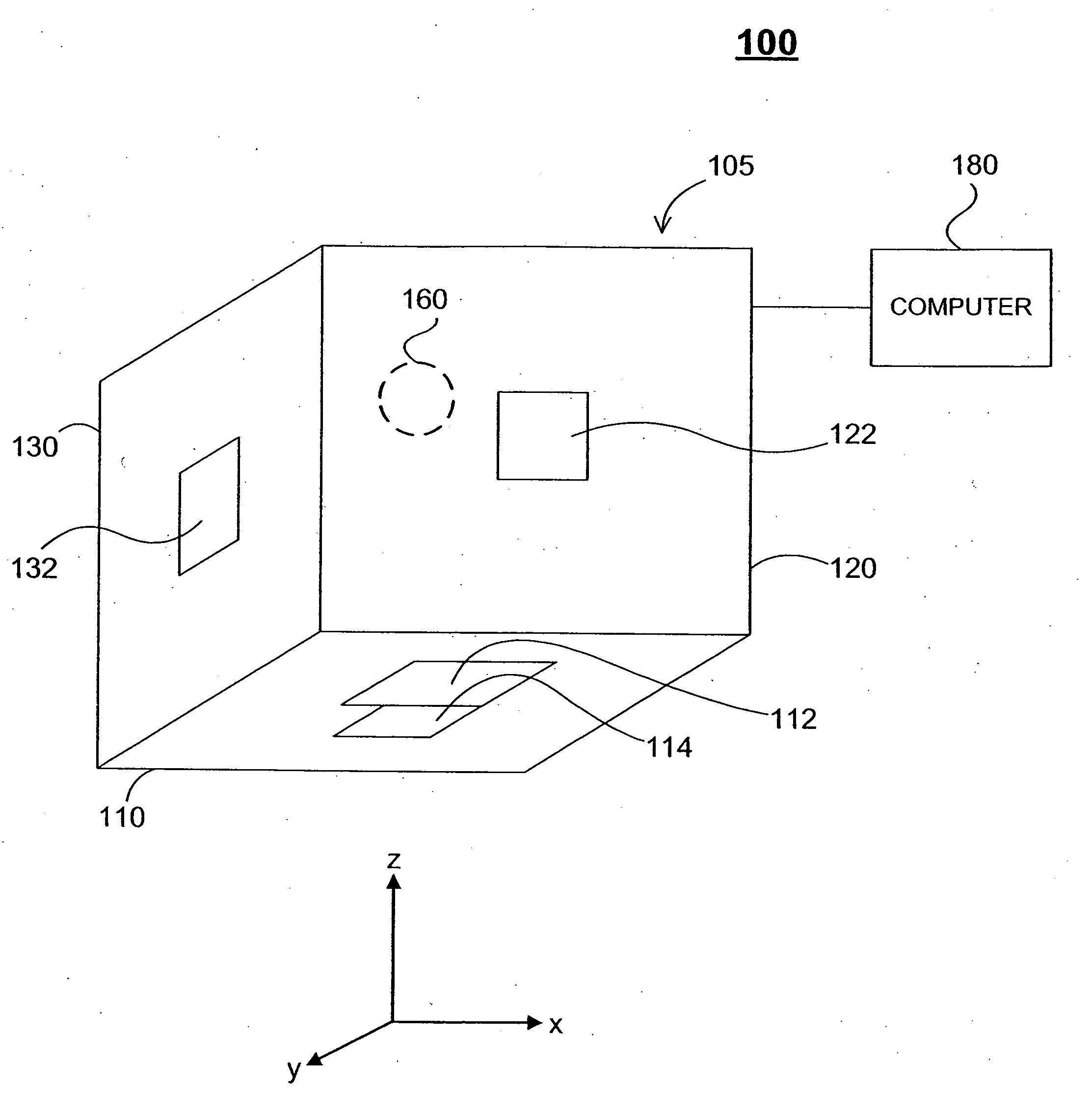
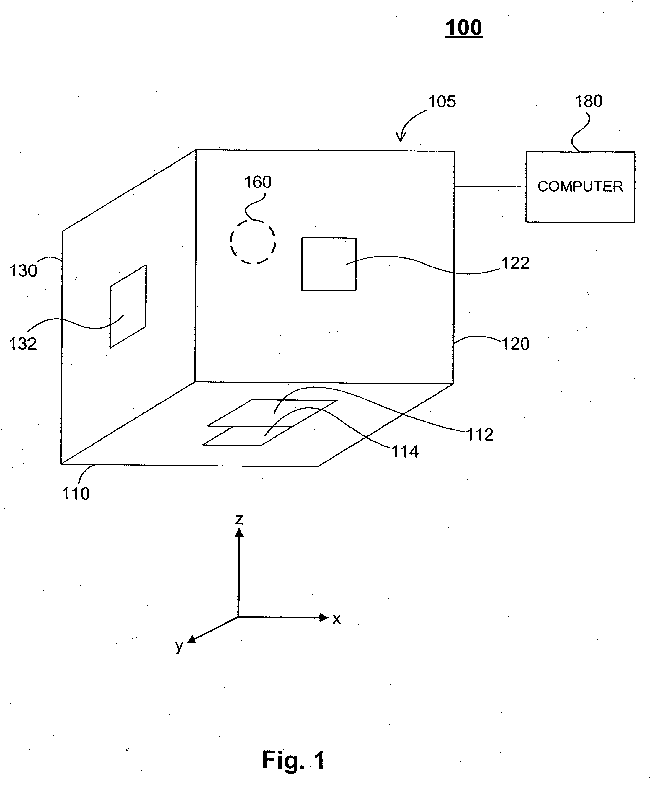
[0022]FIG. 1 is an example of a tracking system 100, in accordance with an embodiment of the invention. The tracking system 100 comprises a sensing device 105, a target object 160, and a computer 180. The target object 160 may move about within a volume defined by the physical characteristics of the sensing device 105. As long as the target object is located within this vo...


PUM


Abstract

A method is provided for tracking an object's position. One or more semiconductor-based sensors obtain measurements of an energy field associated with the object. A processor applies an algorithm to the measurements to generate one or more values representing a position of the object in a coordinate system. The energy field may comprise a magnetic field, for example. The object may comprise a magnet, for example.

Description

RELATED APPLICATION [0001] This application claims the benefit of U.S. Provisional Patent Application No. 60 / 604,346, which was filed on Aug. 25, 2004 and is incorporated by reference herein.FIELD OF THE INVENTION [0002] The invention relates to systems and methods for tracking the position of an object, and, more particularly, to such systems and methods that use measurement of magnetic / electromagnetic fields and / or signals to obtain information about the object in question. BACKGROUND OF THE INVENTION [0003] There is a constant need for technologies capable of tracking an object's position. In the field of transportation, there is a need to track the position of ships, airplanes, vehicles, etc. Military activities have always required the use of position tracking, such as the need to determine the position of a bombing target. Law enforcement agencies frequently need to determine the position of a subject individual or object, such as a package of contraband, within a search area....

Claims


Application Information

Patent Timeline
IPC IPC(8): G01B7/14
CPCG01B7/003G06F3/046G06F3/0346
Inventor WALLANCE, DANIEL I.BAKER, ANDREA L. M.KRAJEWSKI, WOJCIECH
Owner WALLANCE DANIEL I
Learn More