
Integrated reconfigurable wall system

a wall system and integrated technology, applied in the field of wall moveable system, can solve the problems of difficult reconfiguration or movement without significant amount of labor and dislocation, lack of some or all of these attributes in the previous wall system, and most systems lack the flexibility to quickly change the height of the wall. the effect of increasing the height of the modul

Active Publication Date: 2006-03-23
DIRTT ENVIRONMENTAL SOLUTIONS
View PDF15 Cites 123 Cited by
  • Summary
  • Abstract
  • Description
  • Claims
  • Application Information

AI Technical Summary

Benefits of technology

[0004] In a preferred embodiment, the present wall system comprises at least one module, where each module includes a frame and a plurality of tiles mounted to the frame by means of a tile clip system. Clips are attached to the rear surface of each tile and the tile is then pressed into place, aligning the clips with a capture detail on the horizontal frame stringers. Tiles can span adjacent frames where required. Horizontal frame stringers may include a cantilever channel detail where desired to allow objects to be hung along the width. A single frame comprised of two verticals frame members and a plurality of horizontals stringers mounted to an existing wall by connecting the horizontal members to brackets attached to the existing wall allows tiles to be mounted as a curtain wall on the existing wall. Two frames may be supported back to back within a framework for modules used to divide adjacent work spaces. A spline is attachable to the top of the frame to extend the frame and allow for additional tiles to be added on to increase a module's height if so desired. The spline is also used to connect a different style of frame above the existing frame if so desired. For example, this allows a framed glass module to be attached above a framed wood substrate module. Two adjacent modules are connected using a removable zipper interface. The zipper contains two flexible gasket components. Where tiles will span adjacent frames or meet one another without a gap, the gaskets bend back behind the tiles. Where tiles do not span adjacent frames and a gap is wanted, the gaskets point outward from the frame, between the tiles. At the edge of a module where no other module is to be connected, a starter strip may be placed, wherein the starter strip includes an integral flexible gasket which conforms to the shape of the surrounding environment while providing both light and sound baffling. The cantilever channel between tiles allows for various accessories or mill work to be supported from the outside of the module at convenient locations and to be adjusted as needed.
[0006] The present wall system also includes levelers. Levelers include upper, middle and lower sections. The upper section includes a hollow cylinder which is threaded along the interior, and a flat upper plated perpendicular to the leveler. The middle section is a hollow cylinder where the interior and exterior surfaces are threaded in opposite directions, with a fixed nut at one end of the middle section for adjustment. The lower section includes a solid cylinder threaded to correspond with the middle section, a fixed lower nut and an inverted V-shaped lower plate. The leveler is used by having the flat plate in the upper section engage a continuous channel in an the lowermost extrusion of a module's frame, and the lower plate engaging a continuous universal foot, located beneath each module. The V-shape of the lower plate distributes the weight of the wall in the direction of the connection channels of continuous universal foot. A leveler can be placed at any location along the width of the module, allowing for a plurality of levelers to be used if needed. Along the base of the universal foot is a plurality of grippers, which can be adapted for either carpet or hard flooring surfaces. The attachment of the leveler to the module is secure and without extra fastener requirement of any sort. Sliding the leveler plates into the extrusion channels, followed by the attachment of subsequent vertical members, secures the levelers in place.

Problems solved by technology

Previous wall systems have lacked some or all of these attributes.
Some are difficult to reconfigure or to move without significant amounts of labour and dislocation.
Most systems lack the flexibility to quickly change the height of a wall, or to use or substitute different types of panels, or replace a module in the middle of a wall without taking apart the entire wall.

Method used


Image

  • Integrated reconfigurable wall system
  • Integrated reconfigurable wall system
  • Integrated reconfigurable wall system

Examples


Embodiment Construction

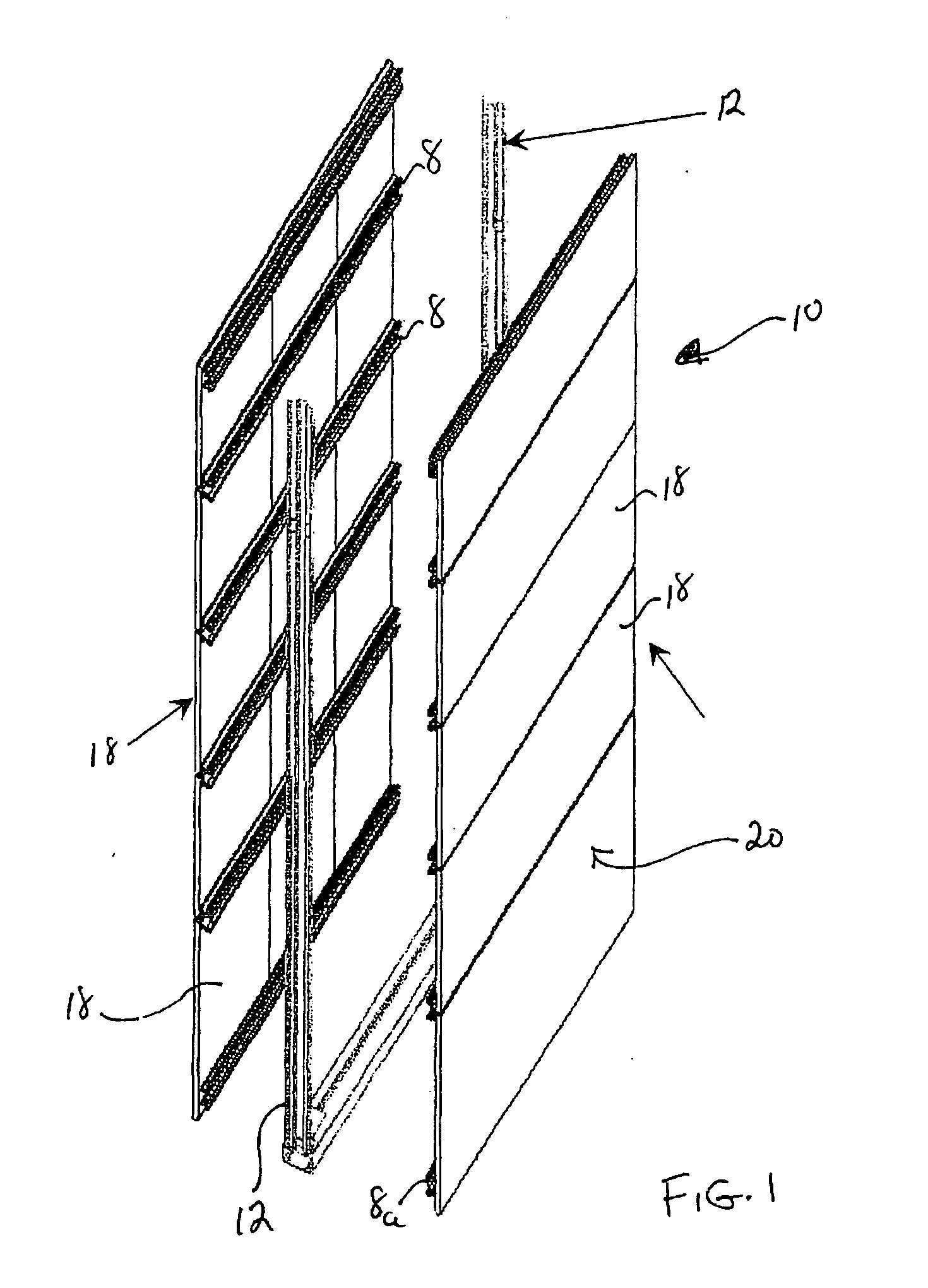
[0047] With reference to FIG. 1, the present invention is directed towards a wall system 10 made up of one or more modules 20. Each module comprises a pair of vertical end frames 12 that will be spaced apart by the desired width of each module. Modules 20 may be clad with tiles 18 and can be one or two sided with a finished wall surface on both sides or a finished wall surface on one side only. Tiles 18 can be made of wood, plastic, metal fabric glass or other material, and end frames 12 may be interconnected by a plurality of horizontal stringers 8 that will be described in greater detail below.

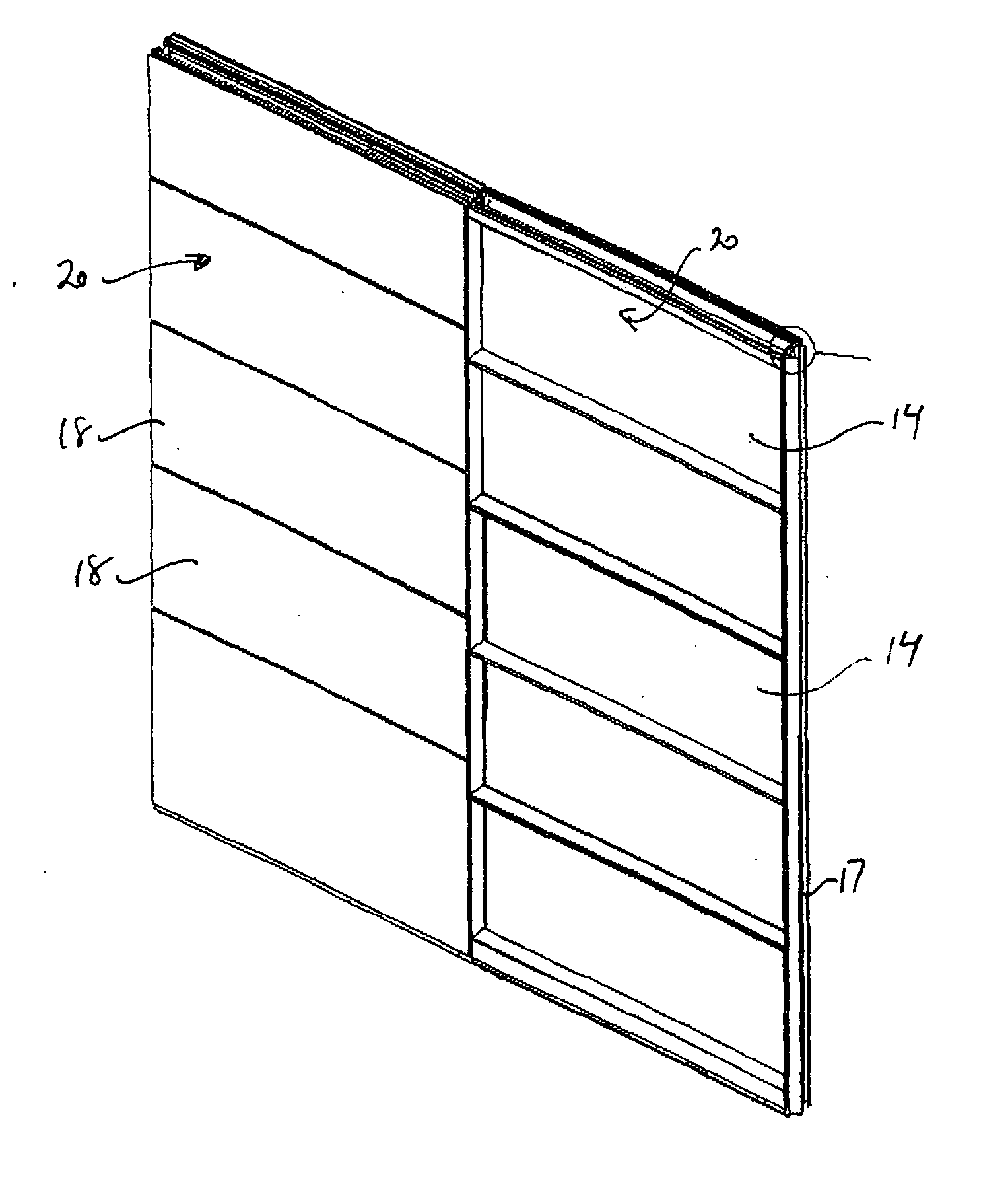
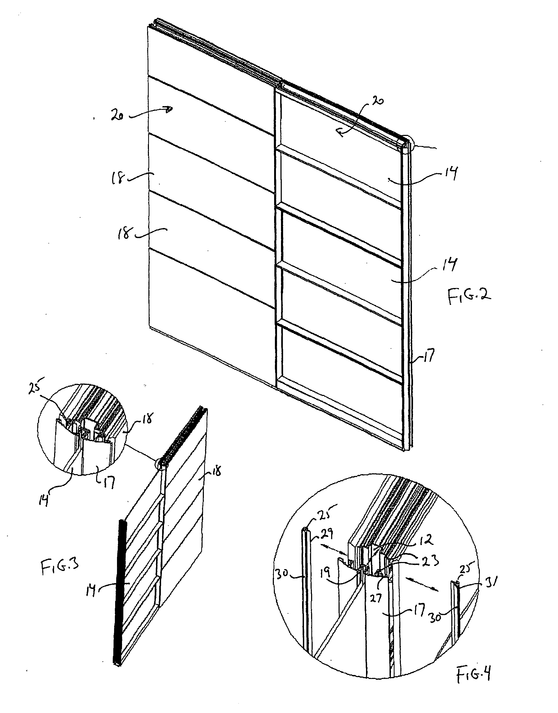
[0048] With reference to FIG. 2, the next adjacent module 20 can be identical to its neighbour, or, as shown in this figure, may consist of two vertical end frames 17 and one or more dividers 14 which can be, for example, glass or plastic if transparency is desired. End frames 17 used for such dividers are shaped as shown most clearly in FIG. 4 and include a notch 19 that receives and holds...


PUM


Abstract

A movable reconfigurable wall system having at least one module having a front and rear surface, the at least one module having: vertical end frames disposed at least at its side edges, each the vertical end frame having a vertically extending flange directed toward the front surface and a vertically extending flange directed toward the rear surface; a plurality of horizontal stringers affixed between the pair of vertical end frames; and an aesthetic surface affixed to the stringers; and a removable connecting strip, the connecting strip adapted to affix about one of the two flanges on one of the vertical end frames and join the one of the two flanges to a corresponding flange on one of a second module, a wall bracket, a finishing trim or a connection post.

Description

FIELD OF THE INVENTION [0001] The present invention relates to a wall moveable system, and more particularly to a reconfigurable moveable wall system comprising reconfigurable components and design elements. BACKGROUND OF THE INVENTION [0002] Wall systems, or dividers as they are sometimes called, are used most commonly in an office environment to separate work areas and to give people privacy where permanent walls are lacking. It is beneficial to have a wall system that is easily movable and easily reconfigured given the ever changing needs and requirements in these environments. Another important aspect in an office is to maximize available space. Aesthetics are also important, including the ability to provide the aesthetic element independently of underlying structural componentry. [0003] Previous wall systems have lacked some or all of these attributes. Some are difficult to reconfigure or to move without significant amounts of labour and dislocation. Most systems lack the flexi...

Claims


Application Information

Patent Timeline
Patent Type & Authority Applications(United States)
IPC IPC(8): E04H1/00
CPCE04B2/7424E04B2002/742E04B2002/749E04B2002/7483E04B2002/7462
Inventor GOSLING, GEOFFSMED, MOGENS
Owner DIRTT ENVIRONMENTAL SOLUTIONS
Learn More