
Bone cutting apparatus

a cutting device and bone technology, applied in the field of bone cutting devices, can solve the problems of difficult and pain-taking procedure, often damaged acl, and severe damage to knee joints that require posterior stabilized knee prosthesis,

Inactive Publication Date: 2006-03-16
BIOMET MFG CORP
View PDF21 Cites 169 Cited by
  • Summary
  • Abstract
  • Description
  • Claims
  • Application Information

AI Technical Summary

Benefits of technology

The invention provides a guide for cutting bone that can be used to make chamfer cuts, posterior cuts, and a box cut in the bone. The guide has a distal portion with a guiding side and a plurality of cutting surfaces at an acute angle to the guiding side for guiding a cutting device to the bone to make chamfer cuts. It also has a second cutting surface at about a right angle to the guiding side for guiding a cutting device to the bone to make posterior cuts. The guide can be positioned on the bone and can include a box-cut shaped opening. The invention also includes a method for guiding a cutting device to the bone to make chamfer cuts, posterior cuts, and a box cut.

Problems solved by technology

The ACL is often damaged in diseased or injured knee joints, and may be removed during total knee replacement.
Knee joints that require posterior stabilized knee prosthesis are typically severely damaged and intercondylar box resection is a challenging and painstaking procedure.
The use of multiple guides increases the duration, complexity and cost of the procedure and is less than desirable.

Method used


Image

  • Bone cutting apparatus
  • Bone cutting apparatus
  • Bone cutting apparatus

Examples


Embodiment Construction

[0034] The following description of various embodiments is merely exemplary in nature and is in no way intended to limit the invention, its application, or uses.

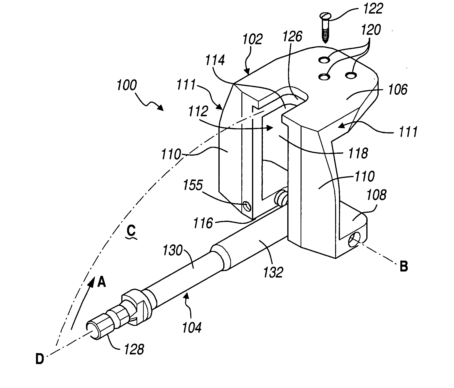
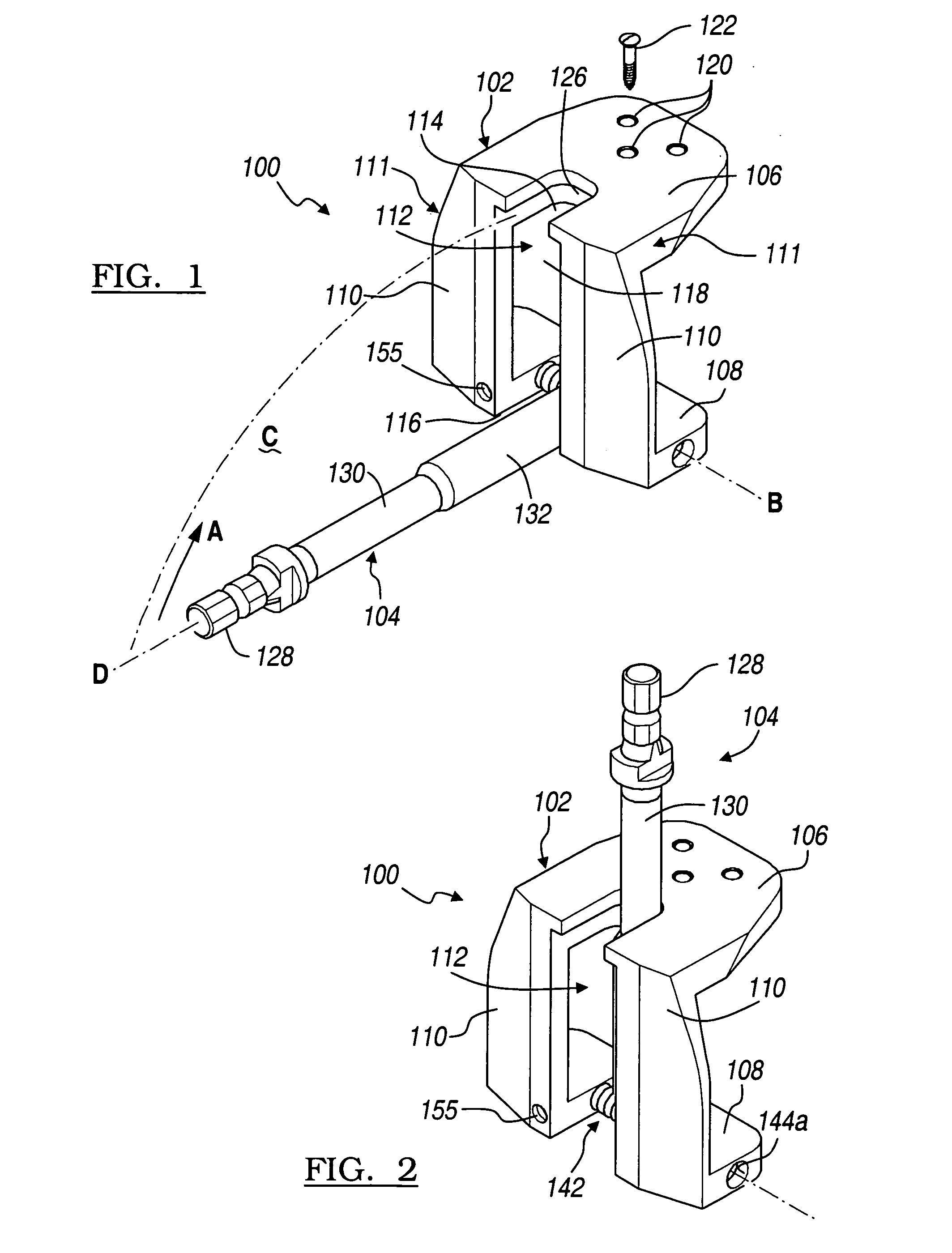
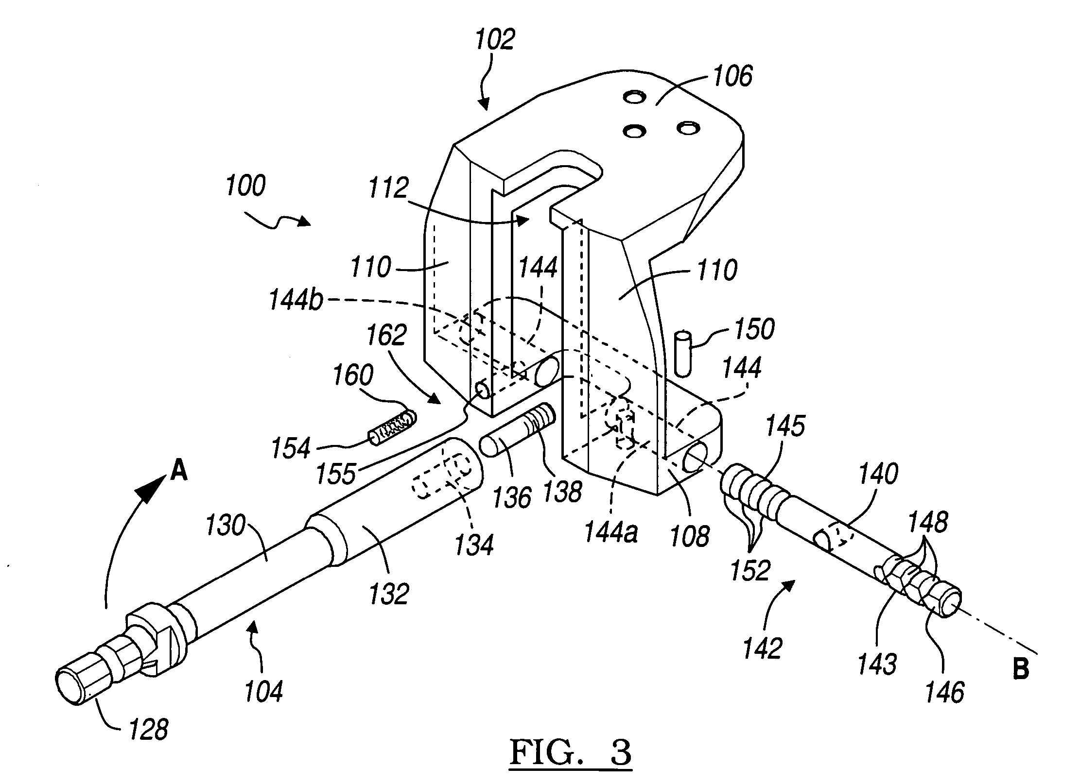
[0035] Referring to FIG. 1, an embodiment of a bone-cutting apparatus 100 according the present invention is shown. The apparatus includes a guide 102 and a mill or reamer or similar cutting tool 104 that can rotate about its own longitudinal axis “D.” The guide 102 may be a generally U-shaped member that includes a flange or anterior portion 106 and a base or posterior portion 108. The flange 106 and the base 108 are joined by a pair of guiding sides 110 at a distal portion 166, which are substantially orthogonal to the flange 106 and the base 108.

[0036] The guide 102 includes a generally “box-cut” shaped opening 112, which is defined by a U-shaped flange cutout 114, a U-shaped base cutout 116 and a rectangular spacing 118 between the guiding sides 110. The box-cut opening 112 is substantially sized and shaped to conform ...


PUM


Abstract

A guide for cutting a bone comprising an anterior portion and a distal portion orientated at about a right angle to the anterior portion. The distal portion includes a guiding side, a distal surface at the guiding side, a box-cut shaped opening defined by the guiding side, a plurality of first cutting surfaces disposed at the guiding side at an acute angle relative to the distal surface of the guiding side operable to guide a cutting device to the bone to form chamfer cuts in the bone, and a second cutting surface disposed at the guiding side at at least about a right angle to the distal surface operable to guide a cutting device to the bone to form a posterior cut in the bone.

Description

[0001] This application is a continuation-in-part of U.S. patent application Ser. No. 10 / 680,902 filed on Oct. 8, 2003. The disclosure of the above application is incorporated herein by reference.FIELD OF THE INVENTION [0002] The present invention relates to a bone-cutting apparatus and associated method. BACKGROUND OF THE INVENTION [0003] Healthy knee joints include two cruciate ligaments, the anterior cruciate ligament (ACL) and the posterior cruciate ligament (PCL). The ACL is often damaged in diseased or injured knee joints, and may be removed during total knee replacement. It is considered desirable, however, to retain the PCL because of its importance for the stability of the knee during bending. When the PCL is damaged beyond repair or otherwise must be removed, a posterior stabilized knee prosthesis is implanted. This prosthesis includes a femoral component with an intercondylar box-shaped part. Therefore, a similarly box-shaped intercondylar bone portion must be resected fr...

Claims


Application Information

Patent Timeline
Patent Type & Authority Applications(United States)
IPC IPC(8): A61B17/16A61B17/17
CPCA61B17/1675A61B2017/1602A61B17/1764
Inventor CUCKLER, JOHN M.METZGER, ROBERTSCHMIDT, KURT N.SCHLUETER, TREVOR S.MCKALE, JAMES M.SERBAN, RADU
Owner BIOMET MFG CORP
Learn More