Auto-focusing optical system for camera module

a technology of auto-focusing and optical system, which is applied in the direction of camera focusing arrangement, printers, instruments, etc., can solve the problems of limited sharpness of image quality, difficulty in mounting a camera module manufactured according to the related art on a small-sized cellular phone, and difficulty in accurately controlling the position of the lens, etc., to maximize the efficiency of an optical system, reduce the size of the device, and reduce the effect of manufacturing cos

Inactive Publication Date: 2006-03-16
SAMSUNG ELECTRO MECHANICS CO LTD
View PDF3 Cites 29 Cited by
  • Summary
  • Abstract
  • Description
  • Claims
  • Application Information

AI Technical Summary

Benefits of technology

[0029] An object of the present invention is to provide an auto-focusing optical system for a camera module, capable of being manufactured in a small size and obtaining a high resolution.
[0030] Another object of the present invention is to provide an auto-focusing optical system for a camera module, capable of maximizing an efficiency of an optical system and shortening a length of the whole optical system by concentrating a power in case a very small-sized camera module such as a camera phone is required.
[0031] Further another object of the present invention is to provide an auto-focusing optical system for realizing low power consumption.

Problems solved by technology

However, since it is impossible to focus at a specific distance in such a fixed focusing type, there is a limitation in sharpness of image quality.
For that purpose, a necessity for application of a camera module having an auto-focusing unit, a close-shot unit, and an optical zoom unit on a cellular phone has emerged, but there has been difficulty in mounting a camera module manufactured according to the related art on a small-sized cellular phone.
However, according to the camera module of the related art, since a plurality of reduction gears are connected together so that a relative distance between lenses may be changed, it is difficult to accurately control a position of a lens so as to precisely perform a focusing due to reduction in response time and deviation in rotational speed.
Further, since the camera module is big in its size and complicated in its structure, it is difficult to realize an auto-focusing function at an extremely limited space in an inside of a small-sized optical apparatus such as a cellular phone.
Further, since a plurality of lenses is used to obtain a high resolution, manufacturing cost is increased and mechanical operation is required, which increases power consumption.

Method used


Image

  • Auto-focusing optical system for camera module
  • Auto-focusing optical system for camera module
  • Auto-focusing optical system for camera module

Examples


Embodiment Construction

[0052] Reference will now be made in detail to the preferred embodiments of the present invention, examples of which are illustrated in the accompanying drawings.

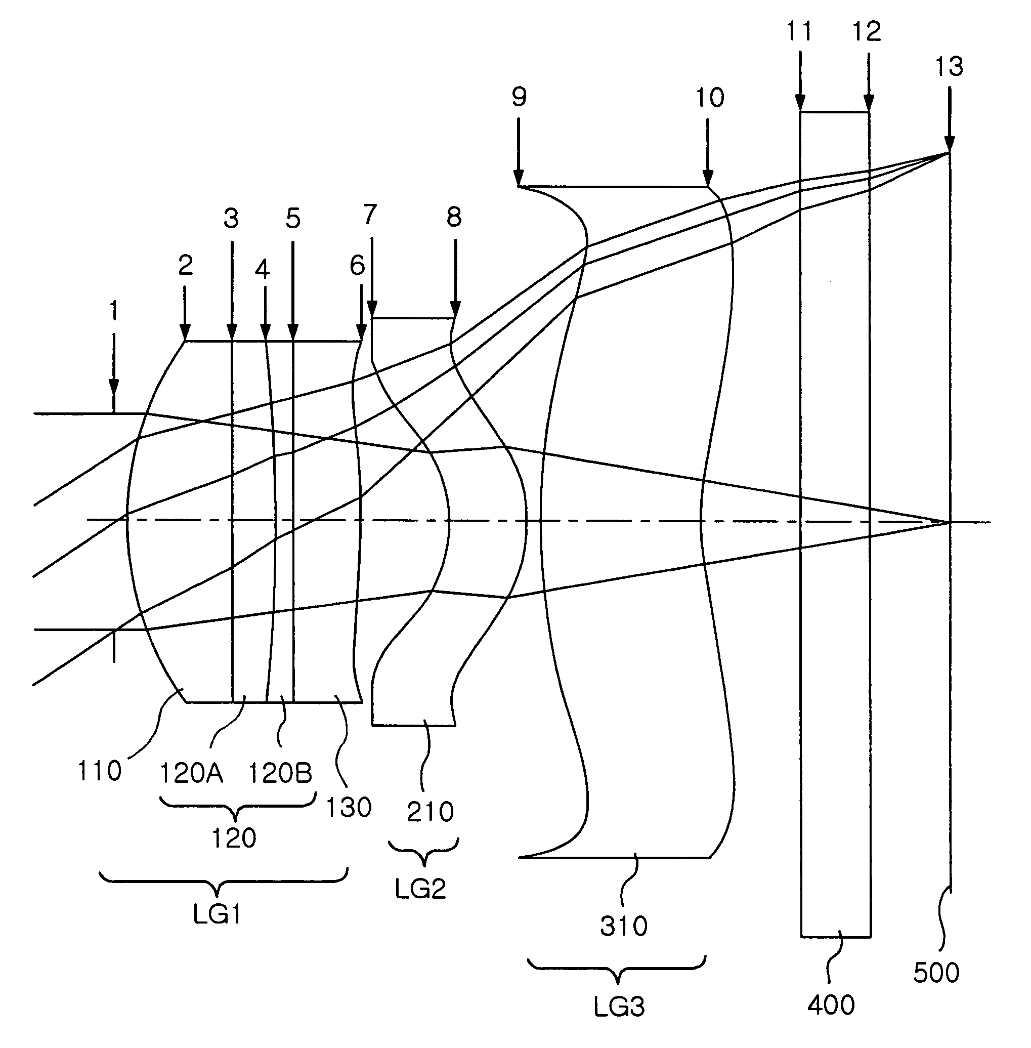
[0053]FIG. 4 is a view illustrating a combination of lens in an optical system according to an embodiment of the present invention. In FIG. 4, the thickness, size, and shape of a lens have been exaggerated more or less for convenience in explanation, and particularly, spherical and aspherical shapes illustrated in FIG. 4 have been given for an embodiment purpose only, and not limited to that specific shape.

[0054] Referring to FIG. 4, an auto-focusing optical system according to an embodiment of the present invention includes, sequentially from an object side: an aperture stop 1 arranged most closely to an object side for removing unnecessary light; a first lens group (LG1) of a plus optical power and including a liquid lens and an aspherical lens having at least one aspherical refraction surface; a second lens group (LG2)...


PUM


Abstract

The present invention relates to an auto-focusing optical system, and more particularly, to an auto-focusing optical system for a camera module, capable of obtaining a high resolution in a small size using a liquid lens whose curvature is varied depending on an applied voltage. In the auto-focusing optical system, a first lens group has a liquid lens whose curvature is varied and having a plus optical power, a second lens group has a plus optical power, and a third lens group has a minus optical power. Thanks to an auto-focusing optical system including a liquid lens according to the present invention, not only a manufacturing in a small size is possibly realized but also a high resolution can be obtained, and power consumption is small.

Description

RELATED APPLICATION [0001] The present application is based on, and claims priority from, Korean Application Number 2004-0069726, filed Sep. 1, 2004, the disclosure of which is hereby incorporated by reference herein in its entirety. BACKGROUND OF THE INVENTION [0002] 1. Field of the Invention [0003] The present invention relates to an auto-focusing optical system, and more particularly, to an auto-focusing optical system for a camera module, capable of obtaining a high resolution in a small size using a liquid lens whose curvature is varied depending on an applied voltage. [0004] 2. Description of the Related Art [0005] Generally, a camera has a plurality of lenses and is configured to adjust an optical focal length by moving each lens to change a relative distance between lenses. Recently, a cellular phone with a built-in camera has emerged and accordingly it has become possible to photograph a still image or a moving picture using the cellular phone. Further, a recent trend is th...

Claims


Application Information

Patent Timeline
Patent Type & Authority Applications(United States)
IPC IPC(8): G02B3/12G03B13/32G03B13/34
CPCG02B3/14G02B13/0035H04N5/2257G03B13/36G02B13/0075H04N23/57G02B13/18
Inventor KIM, TAE YOUNGKIM, YOUNG JUNJO, YOUNG JOO
Owner SAMSUNG ELECTRO MECHANICS CO LTD
Why Eureka
Try Eureka