Phase shifting device
- Summary
- Abstract
- Description
- Claims
- Application Information
AI Technical Summary
Benefits of technology
Problems solved by technology
Method used
Image
Examples
first embodiment
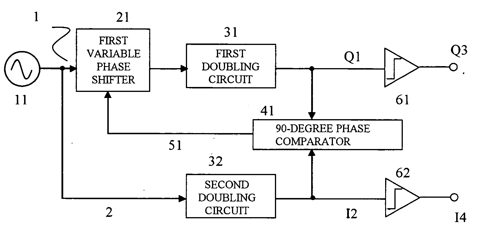
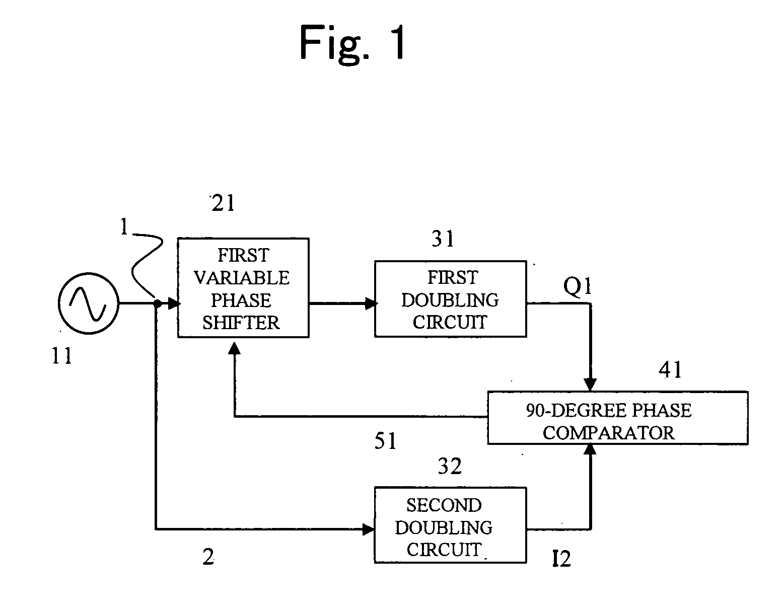
[0065] A 90-degree phase shifting device according to a first embodiment of the present invention is shown in FIG. 1. The 90-degree phase shifting device has a signal source 11; a first variable phase shifter 21 capable of changing the amount of phase shift rotation by a first phase shift control signal 51; a first doubling circuit 31; a second doubling circuit 32; and a 90-degree phase comparator 41. Here, an output from the signal source 11 is split into two parts which serve as a first input signal 1 and a second input signal 2, respectively.
[0066] When the first input signal 1 and the second input signal 2 are written as V1 and V2, respectively, V1 and V2 are defined as follows:
V1=V2=A*exp(jωt),
where A is the amplitude and ω is the angular frequency.
[0067] When the output from the first variable phase shifter 21 is written as V21, V21 is defined as follows:
V21=B*exp(jωt+θ),
where B is the amplitude and θ is the amount of phase shift rotation of the first variable phase sh...
second embodiment
[0075] In the above-described 90-degree phase shifting device of FIG. 1 according to the first embodiment, although a phase shift of exactly 90 degrees can be achieved, the amplitudes are not always equal. While the first input signal 1 passes through the first variable phase shifter 21, the second input signal 2 does not pass through any variable phase shifter; therefore, a large amplitude error occurs between the first output signal Q1 and the second output signal I2.
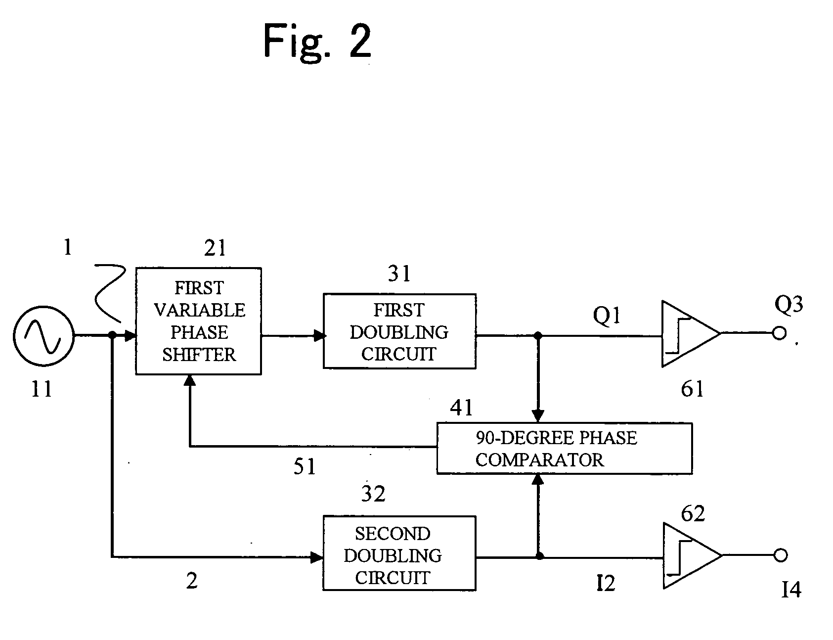
[0076] A second embodiment of the present invention is shown in FIG. 2. The second embodiment provides a 90-degree phase shifting device with which not only an exact 90-degree phase shift can be achieved as in the first embodiment but also equal amplitude output signals can be obtained.
[0077] In the 90-degree phase shifting device, an input of a first gain limiting circuit 61 is connected to a first output signal Q1, and an output from the first gain limiting circuit 61 serves as a third output signal Q3. In additio...
third embodiment
[0079] A third embodiment of the present invention is shown in FIG. 3. The third embodiment provides a 90-degree phase shifting device with which not only an exact 90-degree phase shift can be achieved as in the first embodiment but also equal amplitude output signals can be obtained.
[0080] In the 90-degree phase shifting device, an input of a variable-gain amplifier 71 is connected to a first output signal Q1, and an output from the variable-gain amplifier 71 serves as a third output signal Q3. In addition, a second output signal I2 and the third output signal Q3 are connected to inputs of a level comparator 81. An output from the level comparator 81 is fed back, as a gain control signal 91, to the variable-gain amplifier 71.
[0081] By this, the gain of the variable-gain amplifier 71 is controlled such that the amplitudes of the second output signal I2 and the third output signal Q3 are equal. Accordingly, the third output signal Q3 and the second output signal I2 have equal ampli...
PUM
 Abstract
Description
Claims
Application Information
 - R&D
- Intellectual Property
- Life Sciences
- Materials
- Tech Scout
- Unparalleled Data Quality
- Higher Quality Content
- 60% Fewer Hallucinations
Browse by: Latest US Patents, China's latest patents, Technical Efficacy Thesaurus, Application Domain, Technology Topic, Popular Technical Reports.
© 2025 PatSnap. All rights reserved.Legal|Privacy policy|Modern Slavery Act Transparency Statement|Sitemap|About US| Contact US: help@patsnap.com


