
Oil pump supporting structure of automatic transmission

a technology of automatic transmission and supporting structure, which is applied in the direction of gearing control, gearing elements, gearing ring, etc., can solve the problems of complex process for mounting the oil pump, large structure, and inability to reliably position the pump, so as to prevent vibration and noise of the oil pump

Inactive Publication Date: 2006-03-16
JATCO LTD
View PDF2 Cites 8 Cited by
  • Summary
  • Abstract
  • Description
  • Claims
  • Application Information

AI Technical Summary

Benefits of technology

[0009] It is therefore an object of the present invention to provide an oil pump supporting structure that prevents vibration and noise of an oil pump.
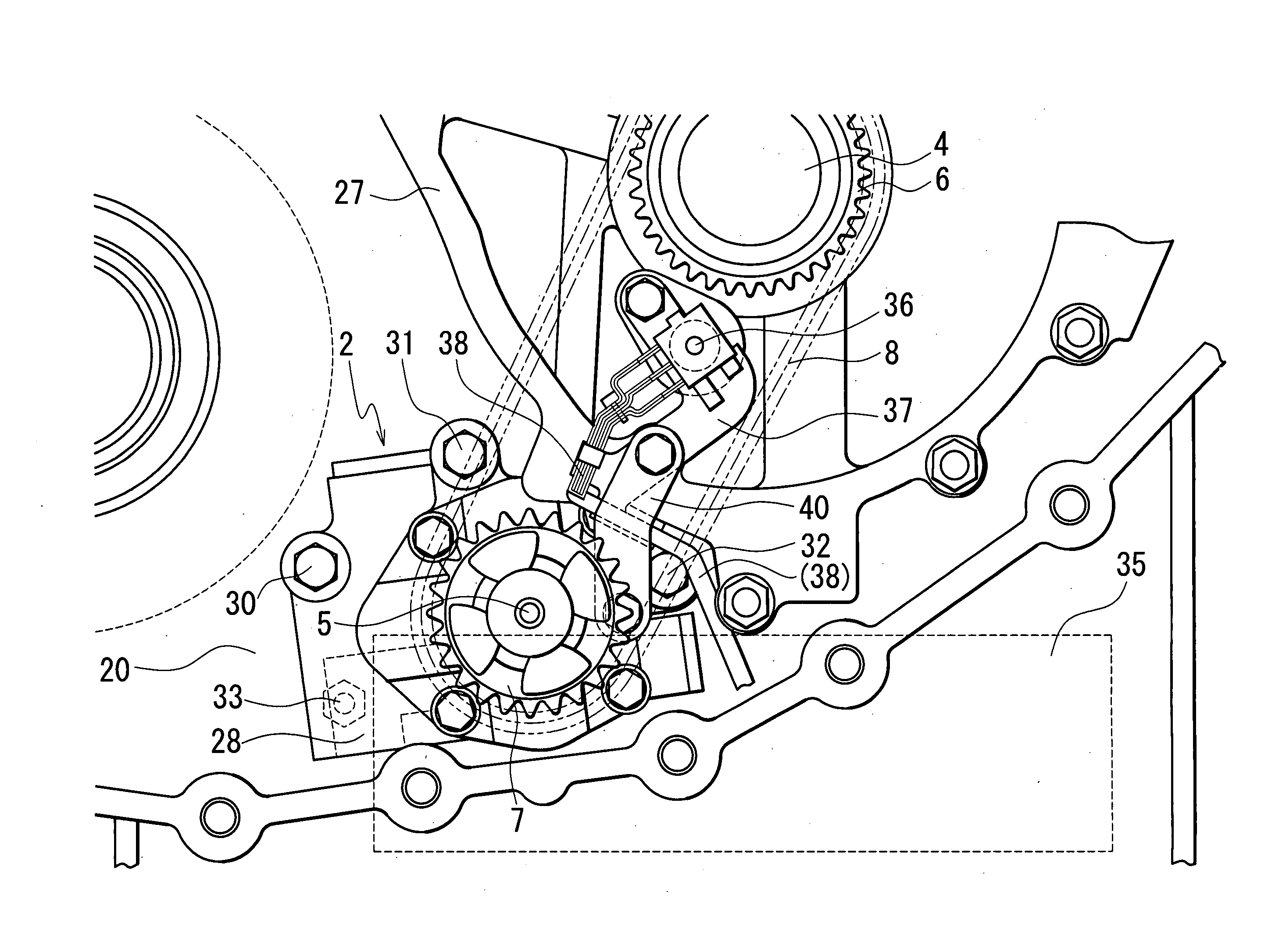
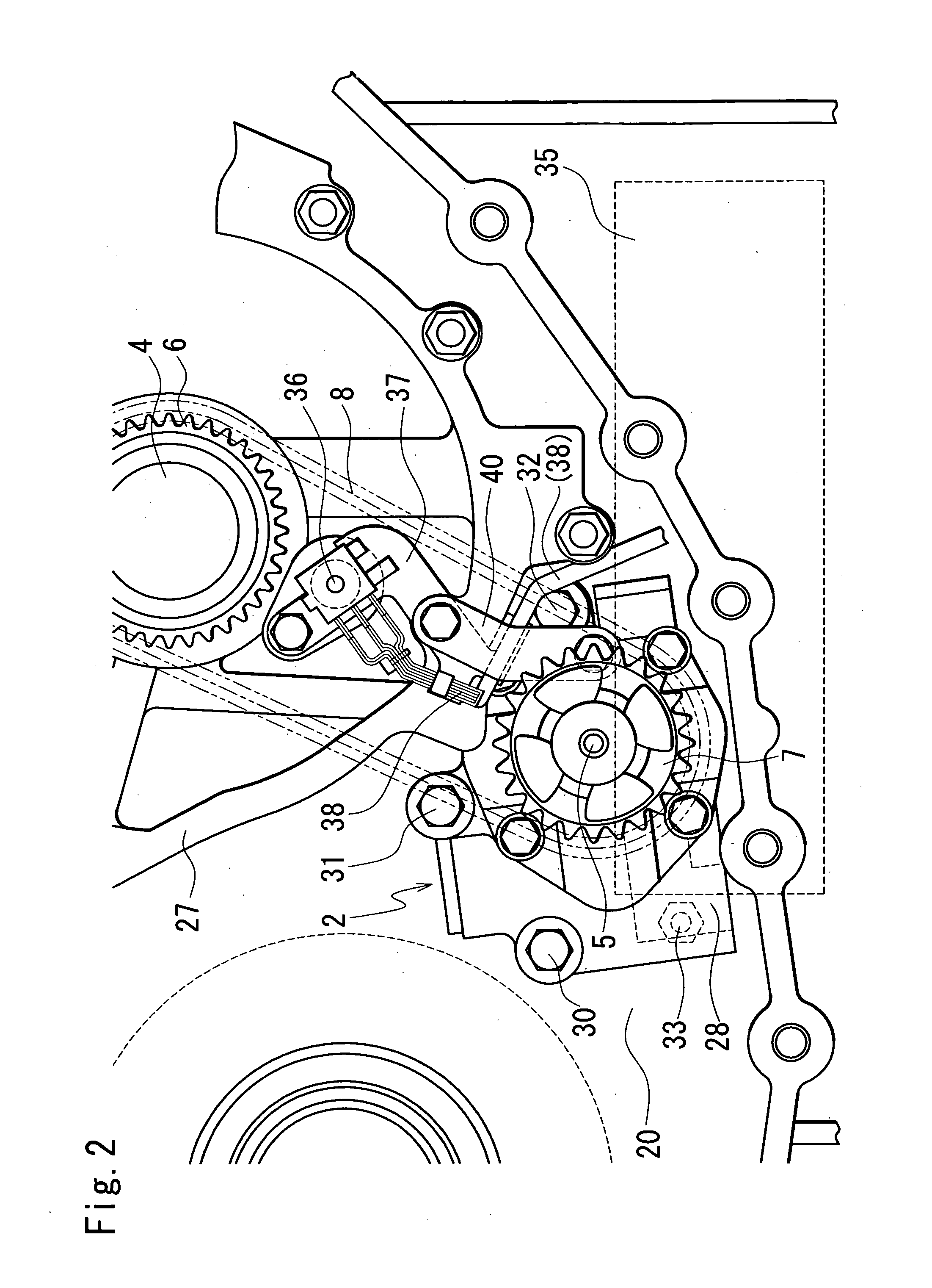
[0011] According to the present invention, since the partition member and the oil pump are fixed to each other by the pump holding member, vibration of the oil pump in the direction of tension of the chain acting when the oil pump is driven can be suppressed to reduce vibration noise.

Problems solved by technology

In the above oil pump supporting structure, however, the oil pump is positioned and fixed by inserting the shaft of the oil pump into the hole of the pump holder, but the process for mounting the oil pump is complicated, and the pump holder must be larger than at least the outer circumference of the pump shaft, making structure large and heavy.
Further, the oil pump cannot be reliably positioned with respect to the rotation direction of the chain, and hence the oil pump is twisted in the same direction as the rotation direction of the driven sprocket, causing vibration and noise.

Method used


Image

  • Oil pump supporting structure of automatic transmission
  • Oil pump supporting structure of automatic transmission
  • Oil pump supporting structure of automatic transmission

Examples


Embodiment Construction

[0017] The present invention will now be described in detail with reference to the drawings showing a preferred embodiment thereof.

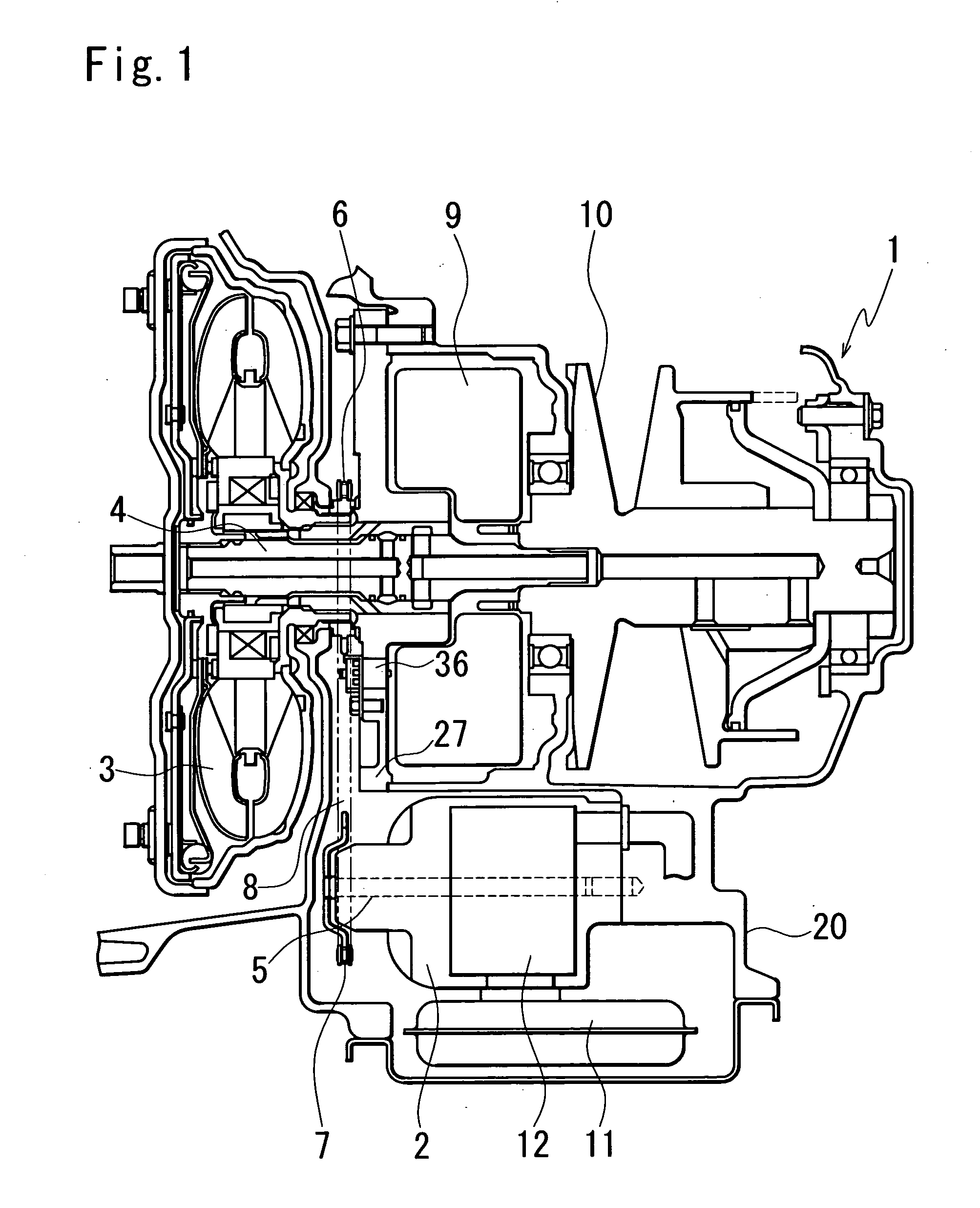
[0018]FIG. 1 is a sectional view showing an oil pump of a belt type continuously variable transmission and its vicinity according to an embodiment of the present invention. FIG. 2 is a front view showing the oil pump and its vicinity according to the embodiment.

[0019] A continuously variable transmission 1 to which power from an engine is input includes an input shaft 4 to which power is input from the engine via a torque converter 3, a forward / backward switching mechanism 9 that changes rotation directions of the power input to the input shaft 4, and a shift mechanism 10 that converts and transmits revolutions to wheels of a vehicle, not shown.

[0020] A vane type oil pump 2 driven by torque from the input shaft 4 is disposed such that an oil pump rotary shaft 5 and the input shaft 4 are in parallel with each other.

[0021] It is preferred that the vane...


PUM


Abstract

There is provided an oil pump supporting structure which can prevent vibration and noise of an oil pump. A pump holding member is disposed in substantially parallel with the tensioning direction of a chain, for connecting a partition member and the oil pump to each other. As a result, vibration occurring in the tensioning direction of the chain when the oil pump is driven can be suppressed to reduce vibration noise.

Description

BACKGROUND OF THE INVENTION [0001] 1. Field of the Invention [0002] The present invention relates to a supporting structure of an oil pump that is disposed apart from an input shaft of an automatic transmission. [0003] 2. Description of the Prior Art [0004] Conventionally, as an oil pump for an automatic transmission, there has been known an oil pump that is disposed apart from an input shaft and driven by rotation of the input shaft via a chain that connects a drive sprocket connected to a pump impeller of the torque converter and a driven sprocket provided in the oil pump. [0005] In a supporting structure of such an oil pump, an end face of the oil pump on a side opposite to the side on which the driven sprocket is provided is connected to a transmission case, and the side of the oil pump on which the driven sprocket is provided is fixed by inserting a pump shaft into a hole of a pump holder connected to the transmission case. [0006] Such an oil pump supporting structure is disclo...

Claims


Application Information

Patent Timeline
Patent Type & Authority Applications(United States)
IPC IPC(8): F01M11/00F16H7/06F16H57/023F16H57/035
CPCF16H61/0031F16H57/0434
Inventor NISHIYAMA, HIROYUKIAMANO, KATSUTOSHI
Owner JATCO LTD
Learn More