Sptical compensatory sheet and method for preparing optically anisotropic layer

a technology of optical anisotropy and compensatory sheet, which is applied in the direction of polarising elements, thin material processing, instruments, etc., can solve the problems of insufficient widening of viewing angle, insufficient ensuring of tilt angle of discotic liquid crystal molecules, and optical leakage in inclined direction, etc., to achieve excellent optical compensatory properties, improve tilt angle, and improve the effect of tilt angl

Inactive Publication Date: 2006-03-09
FUJIFILM CORP
View PDF8 Cites 5 Cited by
  • Summary
  • Abstract
  • Description
  • Claims
  • Application Information

AI Technical Summary

Benefits of technology

[0008] One object of the present invention is to provide methods capable of rapidly preparing optically anisotropic layers formed of hybrid aligned liquid crystal compounds without defects such as schlieren defects. Another object of the present invention is to provide optical compensatory sheets having optically anisotropic layers in which liquid crystal molecules are aligned with improved tilt angle, exhibiting excellent optical compensatory properties. Especially, the present invention has for its object to provide optical compensatory sheets having optically anisotropic layers in which discotic liquid crystal molecules are aligned with improved tilt angle, contributing to broadening the viewing angle of liquid crystal displays (LCD) such as TN-mode and OCB-mode LCD.

Problems solved by technology

However, when the present inventors actually employed these optical compensatory sheets in combination with some kinds of polarization plates, optical leaks were found in the inclined direction, and the viewing angle was not adequately broadened (to the degree that would be theoretically anticipated).
One reason for the inadequate optical compensation function is that the tilt angle of the discotic liquid crystal molecules cannot be adequately ensured.
However, it is difficult to align liquid crystal compounds in mono-domain alignment, in which liquid crystal compounds are uniformly aligned in whole spaces between alignment layer interfaces and air interfaces, by driving force of an alignment layer alone.
Some defects such as schlieren defects occur easily in the layers composed of liquid crystals aligned by driving force of alignment layer alone.
Although shortening time for maturing alignment contributes to raising productivity, it leads to much increased schlieren defects.
The optically anisotropic layers having schlieren defects scatter light, thereby resulting in lowered optical characteristics.

Method used


Image

  • Sptical compensatory sheet and method for preparing optically anisotropic layer
  • Sptical compensatory sheet and method for preparing optically anisotropic layer
  • Sptical compensatory sheet and method for preparing optically anisotropic layer

Examples


example 1

[0292] (Preparation of an Optical Compensatory Sheet)

[0293] A triacetyl cellulose film having a thickness of 100 micrometers and a size of 270 mm×100 mm, “FUJI TAC” manufactured by FUJI FILM, was used as a transparent support. A solution of alkyl-modified polyvinylalcohol, “MP-203” manufactured by KURARAY CO., LTD, was applied to the film in 0.5 micrometers, dried and its surface was subjected to rubbing treatment, to form an alignment layer. The coating liquid containing following components was applied to the alignment layer by a bar-coater. A Coating Solution for an optically anisotropic layer

Compound No. I-1, denoted by the Formula (I)0.6 weight partsTriphenylene liquid crystal (I) disclosed inJP-A No. hei 7-306317 as Compound No. TP-53:100 weight partsEthylene oxide-modified trimethylolpropane9.9 weight partstriacrylate (V#360 made by OsakaOrganic Chemicals (Ltd.))Polymerization initiator (IRGACURE 907 made3.3 weight partsby Ciba-Geigy)Sensitizer (KAYACURE DETX made by1.1 we...

example 13

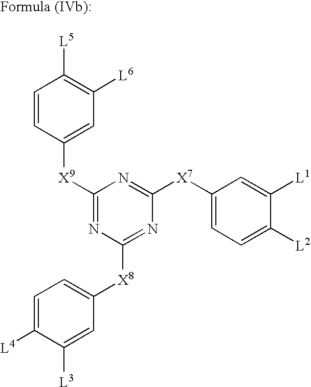
[0302] An optical compensatory sheet was prepared in the same manner as Example 1, except that 4.5 weight parts of 1,3,5-triazin compound shown in Table 2 was used in the place of the 0.6 weight parts of Compound (I-1) and an alignment process as follows was carried out in the place of the alignment process above. The tilt angles shown in Table 2, were estimated in the same manner as Example 1.

(Alignment Process)

[0303] The coated layer was heated up to 120 degrees Celsius for about 20 seconds and after that, the temperature was decreased by 80 degrees Celsius for about 20 seconds. Subsequently the layer was irradiated at the same temperature with UV light of 0.4 J to fix the alignment. The obtained layer had a thickness of 1.75 micrometers. Thus the optically anisotropic layer was prepared and the optical compensatory sheet was obtained.

example 14

[0312] An optical compensatory sheet was prepared in the same manner as Example 13, except that 0.3 weight parts of 1,3,5-triazin compound (IV-2) was used in the place of the 4.5 weight parts of Compound (IV-1). The tilt angles, shown in Table 2, were estimated in the same manner as Example 1.


PUM

PropertyMeasurementUnit
mean tilt angleaaaaaaaaaa
tilt angleaaaaaaaaaa

Abstract

A novel optical compensatory sheet is disclosed. The sheet comprises an optically anisotropic layer thereon comprising at least one compound represented by Formula (I) (R1—X1—)mAr1(—COOH)p, Formula (II): (R2—X2—)nAr2(—SO3H)q or Formula (III): (R—)sAr(—Y)r; where Ar1 denotes an aromatic heterocyclic group or aromatic condensed carbocyclic group, X1 denotes a single bond or divalent linking group, R1 denotes an alkyl group, and m and p are integers from 1 to 4; where Ar2 denotes an aromatic heterocyclic group or aromatic carbocyclic group, X2 denotes a single bond or divalent linking group, R2 denotes an alkyl group, n is an integer from 1 to 4 and q is an integer from 1 to 4; where Ar denotes an aromatic heterocyclic group or aromatic carbocyclic group, R denotes a substituent group, Y denotes sulfo or carboxyl, s is an integer from 0 to 5 and r is an integer from 1 to 4.

Description

FIELD OF THE INVENTION [0001] The present invention belongs to the filed of novel optical compensate sheets and methods for preparing optically anisotropic layers. [0002] Related Art [0003] Optical compensatory sheets are employed in a variety of liquid-crystal displays to eliminate image coloration and broaden the viewing angle. Stretched birefringent films have conventionally been employed as optical compensatory sheets. Further, in recent years, instead of optical compensatory sheets comprised of stretched birefringent films, the use of optical compensatory sheets having an optically anisotropic layer formed of discotic liquid-crystal molecules on a transparent support has been proposed. [0004] The optically anisotropic layer is generally prepared according to a method comprising coating a discotic liquid-crystal composition comprising discotic liquid-crystal molecules on an alignment layer, aligning the discotic liquid-crystal molecules by heating to a temperature exceeding the ...

Claims


Application Information

Patent Timeline
Patent Type & Authority Applications(United States)
IPC IPC(8): C09K19/00C09K19/34C09K19/56G02B5/30G02F1/00G02F1/13363
CPCC09K19/3475C09K19/56C09K2019/328G02B5/3083Y10T428/1005G02F2202/02G02F2413/105Y10T428/10G02F1/0063C09K2323/02C09K2323/00G02F1/13363
Inventor MORISHIMA, SHINICHIYAMANOUCHI, JUNICHITAKAHASHI, MAKOTOICHIHASHI, MITSUYOSHI
Owner FUJIFILM CORP
Why Eureka
Try Eureka