
Apparatus and methods for detecting and locating signals

a technology for locating signals and apparatus, applied in direction/deviation determining electromagnetic systems, navigation instruments, instruments, etc., can solve problems such as inability to accurately determine the boundary line and plane, user-operated search patterns susceptible to human error and long search times, and methods susceptible to multi-path errors.

Inactive Publication Date: 2006-03-09
LUCID DIMENSIONS
View PDF23 Cites 9 Cited by
  • Summary
  • Abstract
  • Description
  • Claims
  • Application Information

AI Technical Summary

Benefits of technology

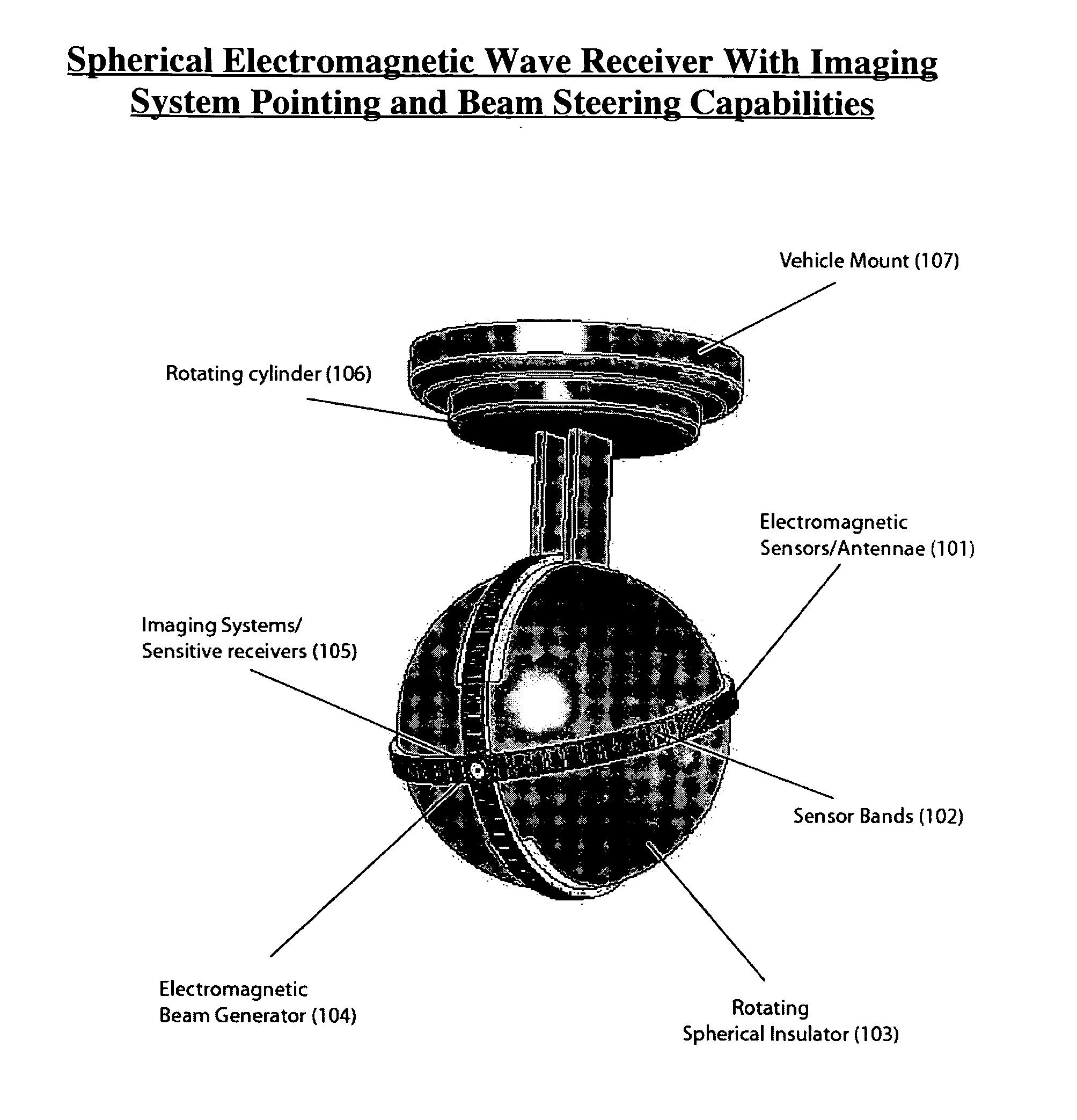
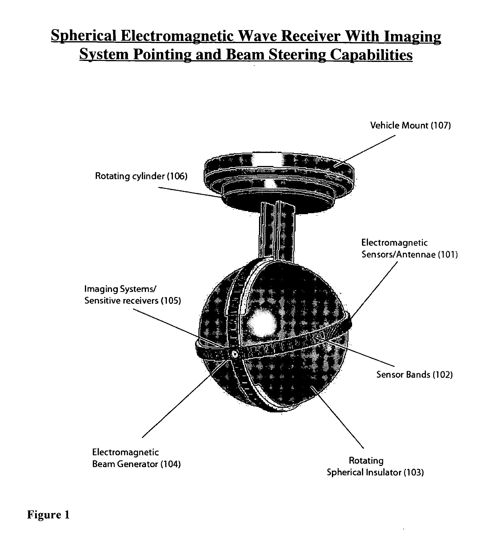
"The present invention provides improved methods and apparatus for detecting and locating signals. The invention uses a spherical receiving element with multiple sensors placed on its surface to detect signals in three dimensions. The sensors are placed in a pattern around the receiving element to determine the direction of the signal. The receiving element can rotate to align with the source of the signal. The invention can be used in various applications such as geometrical sensing, target tracking, and navigation systems. The invention offers a more accurate and efficient way to detect and locate signals in three dimensions."

Problems solved by technology

This method involves user-operated search patterns susceptible to human error and lengthy search times in emergency or time-critical scenarios.
The method susceptible to multi-path errors associated with reflecting waves from the surrounding environment.
These imaging systems are limited to a specific field of view (FOV) and incorporate scanning algorithms and image processing techniques for target tracking and identification.
The drawbacks of conventional imaging systems are detailed in The Handbook of Infrared Technology, “with a limited field-of-view system, a large distance is required to view a large area.
But then the target becomes very small and may be hard to find.
Shorter distances mean that a smaller area is viewed and overall search time is significantly increased.” These limitations on contemporary imaging systems cause significant difficulties when monitoring a wide field of regard for infrared sources.
In addition, sources which are near the 120° range of the system become obscured on the image plane and must be corrected with image processing algorithms.
The combination of wide FOV, focus time, image processing algorithms, and multiple sensors creates a complex, high-cost system with many components to determine the 3D location of an IR source.
Gaseous targets are notorious for scattering incoming beams and discouraging accurate analysis.
Planar techniques used to acquire the returned signals are prone to multi-path errors resulting from scattering.
Unintended reflecting objects will interfere with the analysis of intended objects.

Method used


Image

  • Apparatus and methods for detecting and locating signals
  • Apparatus and methods for detecting and locating signals
  • Apparatus and methods for detecting and locating signals

Examples


embodiment — 3d

Embodiment—3D Transmit Receive Scanning Systems

[0068] LIDAR systems using light wave frequencies can also be incorporated into the spherical receiving device. The system can emit various frequencies depending on the specific application. The receivers on the sphere will then collect waves returning from the reflecting object. Physical reflecting phenomenon such as Rayleigh and Raman scattering will be incorporated into the systems to determine the desired reflected wavelengths. In applications that search for specific gaseous particles, sensors will be used to receive the specific reflected frequency. The device will have the capability to scan various objects (including toxic, biological, and atmospheric) to find the size and density distribution. The size of the clouds will be derived by scanning and searching for boundary points where specific wavelengths (associated with reflecting particles) do not reflect back to the receiver. The density distribution of the cloud will be dete...


PUM


Abstract

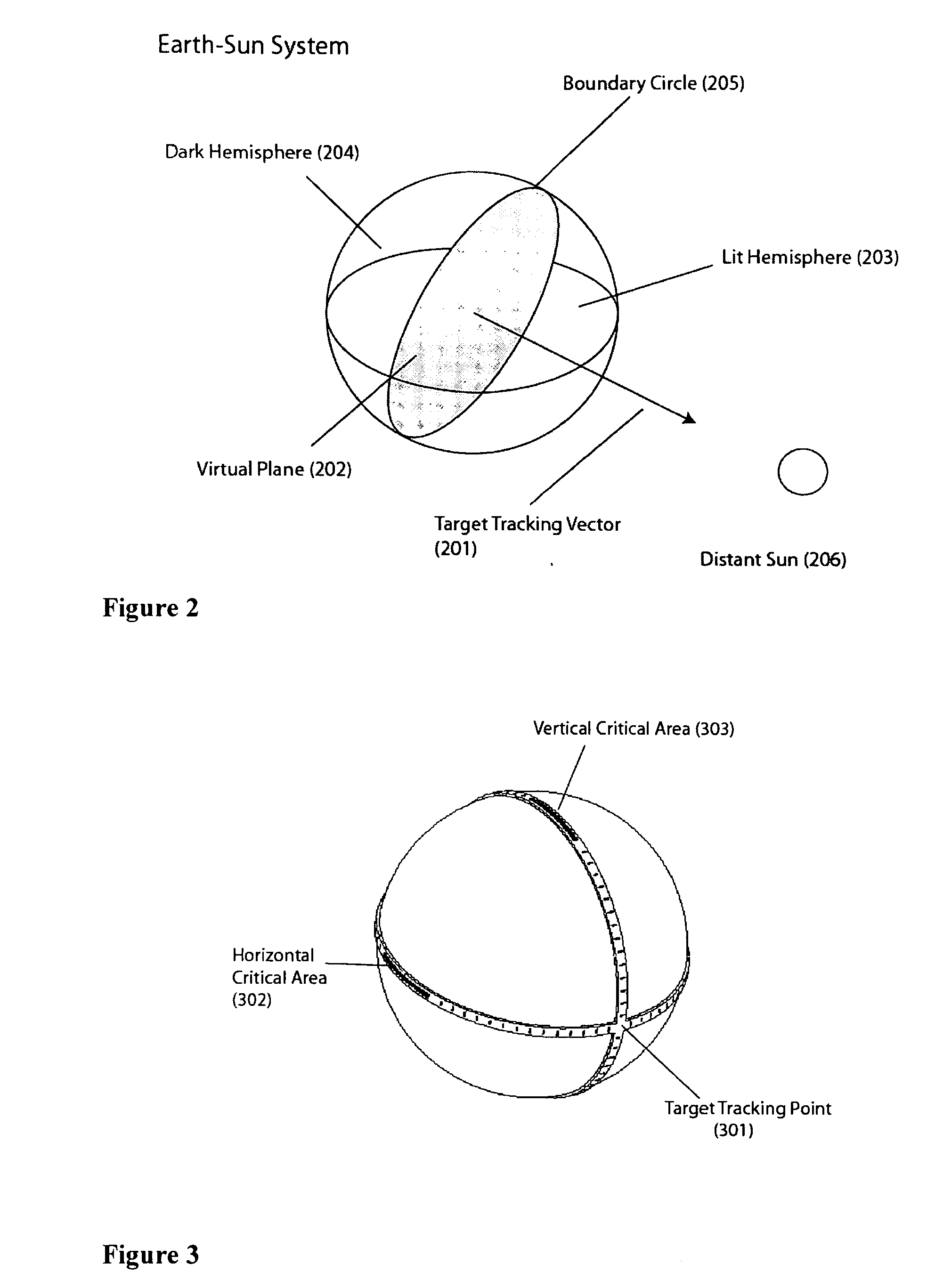
A discrete three-dimensional receiving element has multiple sensors scattered over its surface to detect and locate a signal. The sensors facing the signal detect the signal, and a boundary line is drawn between the sensor which detect the signal and those which don't. The strength of signal may also be detected. A plane is drawn through the receiver element, and the direction of the signal is determined as generally perpendicular to the plane, in the direction of the sensors which are receiving the signal. Distance to the source may also be determined based on signal strength. The location of the signal source may be transmitted to a remote location, or the receiver may direct an electromagnetic beam toward the source to detect further information about the source.

Description

BACKGROUND OF THE INVENTION [0001] 1. Field of the Invention [0002] The present invention is directed to methods and apparatus for detecting and locating signals. More specifically, the present invention is directed to methods and apparatus for detecting and locating signals with a three dimensional receiving element having sensors surrounding its surface. [0003] 2. Description of the Related Art Overall Methods to Locate EM in 3D [0004] Current methods to locate electromagnetic waves in three dimensions rely on intensity, wavelength and phase measurements using planar sensor arrays combined with signal and image processing algorithms. In lower frequency systems, measurements taken by planar sensor arrays are correlated to find the 3D location of electromagnetic wave sources. By measuring the phase shift of waves between sensors, the position of the source can be triangulated. Higher frequency systems in the visible light and infrared range typically use imaging system to determine...

Claims


Application Information

Patent Timeline
Patent Type & Authority Applications(United States)
IPC IPC(8): G01S5/04
CPCG01S3/043G01S3/28G01S3/42G01S3/781G01S5/28G01S3/801G01S3/8034G01S5/12G01S5/16G01S3/783
Inventor RIEL, RYAN DAVIDCALIHMAN, ADAM ETHAN
Owner LUCID DIMENSIONS
Learn More