Optical communication apparatus, optical communication system and method for transmitting optical signal

a communication apparatus and optical communication technology, applied in multiplex communication, multiplex communication, wavelength-division multiplex systems, etc., can solve the problems of serious signal waveform distortion, cost of converting all wavelength-division-multiplexed signals, and the signal cannot be properly received by the receiving terminal station, etc., to achieve the best signal transmission performance

Inactive Publication Date: 2006-03-02
NEC CORP
View PDF4 Cites 36 Cited by
  • Summary
  • Abstract
  • Description
  • Claims
  • Application Information

AI Technical Summary

Benefits of technology

[0056] It is an object of the present invention to provide an optical communication apparatus, an optical communication system, and an optical transport method which require no auxiliary DCM to be provided for each wavelength, do not need to change an amount of dispersion compensation even when a new wavelength path is added, and are capable of achieving best signal transmission performance by setting accumulated dispersion of an optical signal when the optical signal is received to an optimum value.
[0060] With the above arrangement, the receiving dispersion compensating module adjusts the accumulated dispersion of the wavelength-division-multiplexed signal such that the accumulated dispersion has an optimum value at a receiver for receiving optical signals in respective wavelength channels which are dropped from the wavelength-division-multiplexed optical signal. The auxiliary dispersion compensating module is provided in a path for the through wavelength group. The auxiliary dispersion compensating module adjusts the accumulated dispersion of the wavelength-division-multiplexed optical signal in the through wavelength group by canceling out the accumulated dispersion adjusted by the receiving dispersion compensating module. Therefore, the accumulated dispersion of the dropped wavelength group has an optimum value, the accumulated dispersion of the wavelength-division-multiplexed optical signal in the through wavelength group and the accumulated dispersion of the wavelength-division-multiplexed optical signal in the added wavelength group are eliminated, and the accumulated dispersion of the through wavelength group and the accumulated dispersion of the added wavelength group are equalized to each other in the multiplexing unit.
[0062] With the above arrangement, the receiving dispersion compensating module adjusts the accumulated dispersion of the wavelength-division-multiplexed signal supplied as an input optical signal such that the accumulated dispersion has a value of zero. The auxiliary dispersion compensating module is provided in a path for the dropped wavelength group. The auxiliary dispersion compensating module adjusts the accumulated dispersion of the wavelength-division-multiplexed optical signal in the dropped wavelength group such that the accumulated dispersion has an optimum value at a receiver for receiving optical signals in respective wavelength channels which are dropped from the wavelength-division-multiplexed optical signal. Therefore, the accumulated dispersion of the dropped wavelength group has an optimum value, the accumulated dispersion of the wavelength-division-multiplexed optical signal in the through wavelength group and the accumulated dispersion of the wavelength-division-multiplexed optical signal in the added wavelength group are eliminated, and the accumulated dispersion of the through wavelength group and the accumulated dispersion of the added wavelength group are equalized to each other in the multiplexing unit.
[0064] The optimum value of accumulated dispersion may be a value for minimizing a bit error rate at the time the wavelength-division-multiplexed optical signal is received, or may be a value other than zero.

Problems solved by technology

When the signal suffers accumulated dispersion, different frequency components of the signal are delayed by different amount, resulting in a serious signal waveform distortion.
If the accumulated dispersion is too large, then the signal cannot properly received by the receiving terminal station.
Thereafter, as the transmission capacity per link greatly increased according to the wavelength division multiplexing technology, the cost of a process of converting all wavelength-division-multiplexed signals into electric signals at an input section of each node, editing the electric signals, and then generating and outputting all wavelength-division-multiplexed signals again become burdensome.
However, the arrangement shown in FIG. 4 is disadvantageous in that when add / drop settings are changed, the optical filters need to be taken into and out of working positions, and instantaneously interrupt all the through signals.
Therefore, the arrangement shown in FIG. 4 is not suitable for use in OADM applications for dynamically changing add / drop settings.
Though the optical patch code connections are best from the standpoint of structural costs, they are costly in terms of man-hours, tend to suffer setting errors if the number of wavelengths handled increases, and are not freely capable of selecting any desired wavelengths to be added and dropped.
If signals having such different values of accumulated dispersion are produced in a plurality of OADM nodes, then it is difficult to manage the values of accumulated dispersion.
However, this practice faces a dilemma in that since the value of accumulated dispersion at the time the signal is received is not optimum, the transmitted signal cannot have its best performance unlike the data shown in FIG. 7, and a margin for dispersion variations is reduced.
However, it is generally too costly to provide as many auxiliary DCMs 60 as the number of wavelengths involved, and the advantage of being capable of fine adjustment is not universal because it poses undue operational costs to optimize the fine adjustment capability to every application.
The algorithmic process is advantageous in that it requires no special hardware, but is disadvantageous in that as the number of wavelength paths increases, a process of finding a combination of optimum dispersion values compensation is practically infeasible, and it is difficult to handle a change in wavelength path settings because the addition of a new wavelength path needs the amount of dispersion compensation to be changed for the entire system.
Replacing a DCM requires a temporary circuit disconnection and results in an added cost due to the addition of a new DCM to replace the DCM.

Method used


Image

  • Optical communication apparatus, optical communication system and method for transmitting optical signal
  • Optical communication apparatus, optical communication system and method for transmitting optical signal
  • Optical communication apparatus, optical communication system and method for transmitting optical signal

Examples


1st exemplary embodiment

[0118] Optical communication apparatus according to a first embodiment of the present invention, which has two MUXs, will be described below with reference to FIGS. 15 through 18.

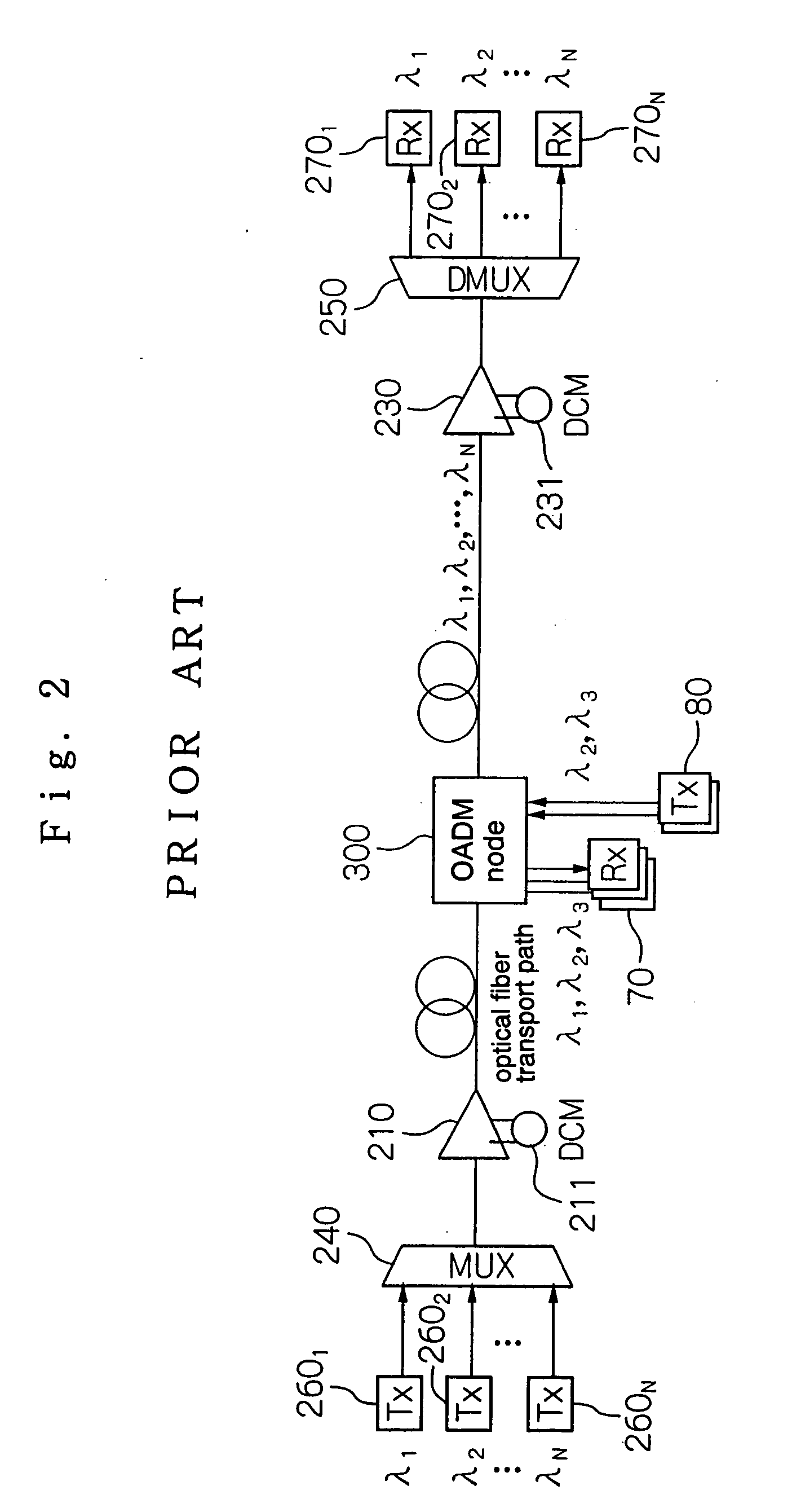
[0119] According to the first embodiment, the principles of the present invention are applied to the conventional OADM node shown in FIG. 3 which is currently in most widespread use. The optical communication apparatus according to the first embodiment has new MUX 41 in addition to the conventional arrangement, thereby having two MUXs 40, 41 to provide a path for an added wavelength group, and also has auxiliary DCM 60 (or 61) inserted in the path for an added wavelength group. The arrangement according to the first embodiment makes it possible to provide different values of dispersion when a wavelength-division-multiplexed optical signal is transmitted and received.

[0120] Though the conventional arrangement has single MUX 40, the optical communication apparatus according to the first embodiment has two M...


PUM


Abstract

The present invention relates to optical communication apparatuses such as OADM node, or OXC node. A receiving dispersion compensating module adjusts the accumulated dispersion of a wavelength-division-multiplexed optical signal such that the accumulated dispersion has an optimum value at a receiver for receiving optical signals in respective wavelength channels which are dropped from the wavelength-division-multiplexed optical signal. An auxiliary dispersion compensating module is provided in a path for an added wavelength group. The auxiliary dispersion compensating module applies the same value of dispersion as the accumulated dispersion adjusted by the receiving dispersion compensating module, to a wavelength-division-multiplexed optical signal in the added wavelength group. Therefore, the accumulated dispersion of a dropped wavelength group has an optimum value, and the accumulated dispersion of a through wavelength group and the accumulated dispersion of the added wavelength group are equalized to each other in a multiplexer.

Description

BACKGROUND OF THE INVENTION [0001] 1. Field of the Invention [0002] The present invention relates to an optical communication system for transmitting a wavelength-division-multiplexed optical signal comprising a plurality of multiplexed optical signals having respective different wavelengths according to the wavelength division multiplexing technology, and more particularly to an optical communication apparatus, an optical communication system, and an optical transport method for an OADM (Optical Add-Drop Multiplexing) node which adds and drops an optical signal having a desired wavelength to and from a wavelength-division-multiplexed optical signal comprising a plurality of multiplexed optical signals having respective different wavelengths, and passes such a wavelength-division-multiplexed optical signal, and an OXC (Optical cross Connect) node which adds and drops an optical signal having a desired wavelength to and from a wavelength-division-multiplexed optical signal comprising...

Claims


Application Information

Patent Timeline
IPC IPC(8): H04B10/12H04B10/2507H04B10/2525H04B10/27H04B10/278H04B10/29H04J14/00H04J14/02
CPCH04B10/25133H04J14/02H04J14/0204H04J14/0213H04J14/0209H04J14/0212H04J14/0206
Inventor YANO, YUTAKA
Owner NEC CORP
Why Eureka
Try Eureka