Electric incandescent lamp

a technology of incandescent lamps and support bodies, which is applied in the direction of electric discharge lamps, basic electric elements, electrical equipment, etc., can solve the problem of not being able to achieve adequate vibration strength with the aid of such support bodies

Inactive Publication Date: 2006-03-02
PATENT TREUHAND GESELLSCHAFT FUR ELECTRIC GLUEHLAMPEN MBH
View PDF6 Cites 2 Cited by
  • Summary
  • Abstract
  • Description
  • Claims
  • Application Information

AI Technical Summary

Benefits of technology

[0003] The object is to provide an electric incandescent lamp having increased vibration strength.
[0005] The electric incandescent lamp according to the invention has an incandescent filament, arranged inside a transparent lamp vessel, and supply leads for the incandescent filament, at least one of the supply leads being provided with at least one strut. By contrast with the support body, designed as a coil, in accordance with the prior art, the at least one strut effects a reinforcement of the supply lead equipped with it. For example, supply lead sections that are bent or angled away are bridged by the at least one strut. As a result, in the case of vibrations the amplitude of the deflection of the incandescent filament from its equilibrium position is reduced, and the vibration strength of the incandescent lamp is increased.

Problems solved by technology

It has emerged that it is impossible with the aid of such support bodies to achieve an adequate vibration strength for incandescent lamps that are used in vehicle headlights.

Method used


Image

  • Electric incandescent lamp
  • Electric incandescent lamp
  • Electric incandescent lamp

Examples


Embodiment Construction

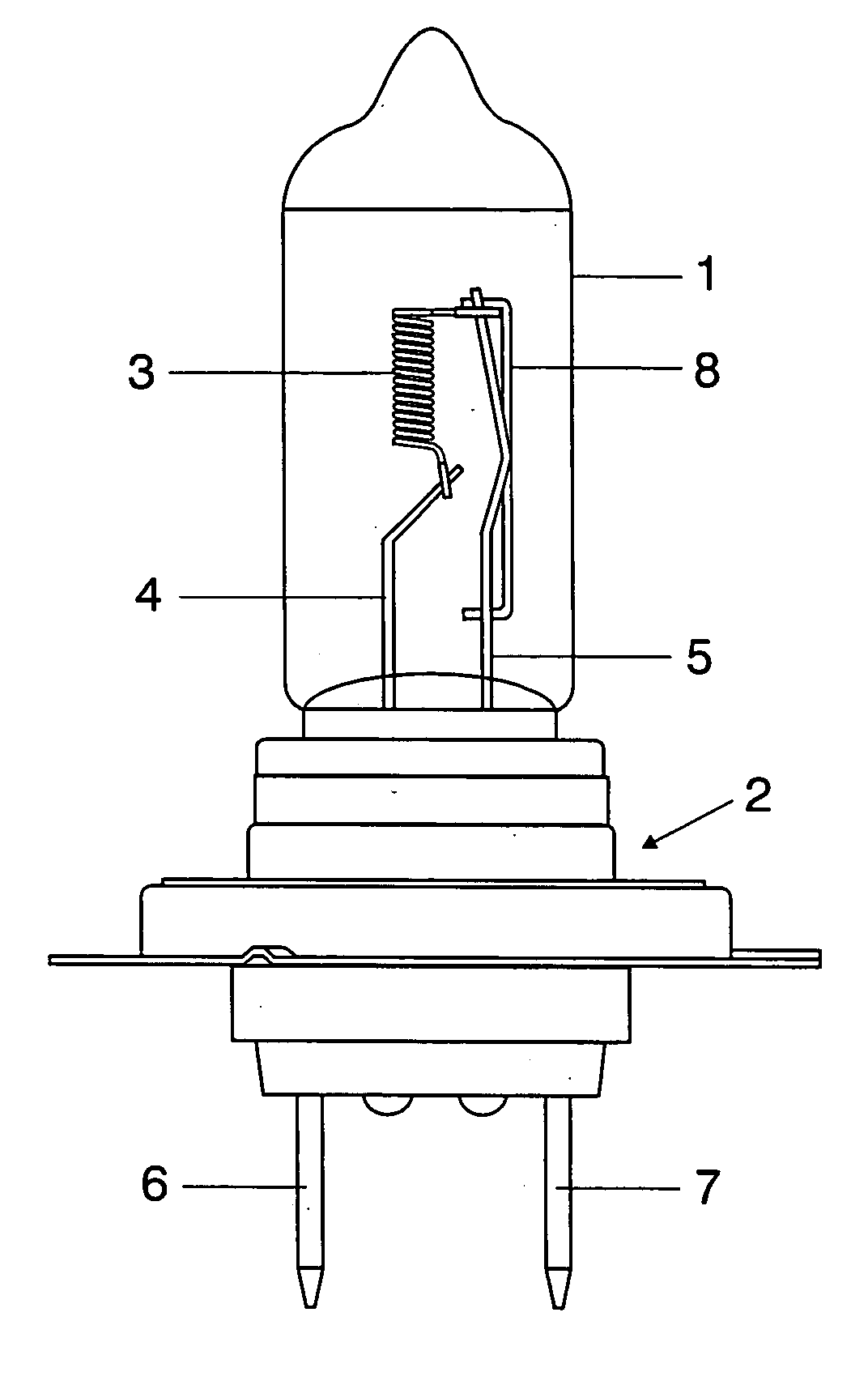
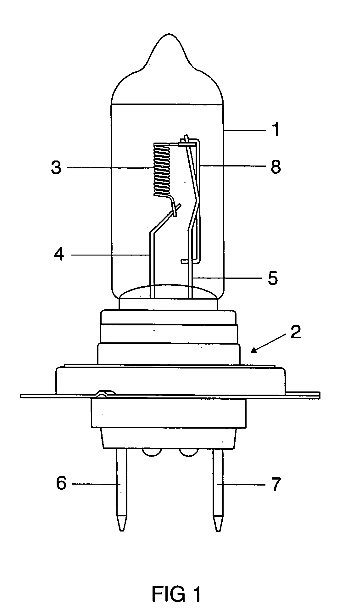
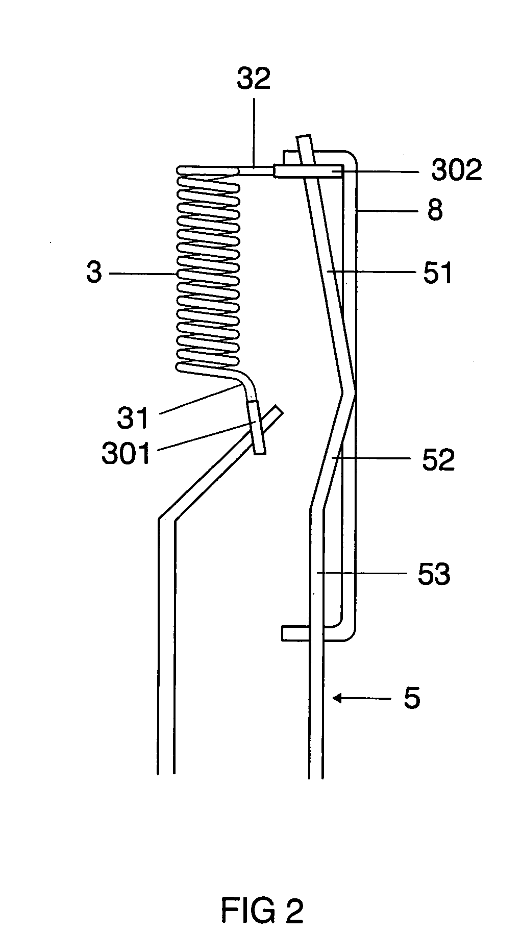
[0011] The incandescent lamp according to the invention depicted in FIG. 1 is a tungsten halogen lamp for a vehicle headlight, in particular an H7 lamp. This lamp has a vitreous, substantially cylindrical lamp vessel 1 that is provided at one end with a metallic base 2. Arranged inside the lamp vessel 1 is an axially aligned incandescent filament 3 whose filament outgoing feeders 31, 32, sheathed with a molybdenum tube 301, 302, are each welded to a supply lead wire 4, 5. The two supply lead wires 4, 5 are respectively connected in an electrically conducting fashion to an electric terminal 6, 7 of the base 2. The supply lead wire 5 connected to the filament outgoing feeder 32 remote from the base is equipped with a strut 8 that is welded at three points to the supply lead wire 5. Both the strut 8 and the supply lead wire 5 are designed as a molybdenum wire with a thickness of 0.7 mm. The strut 8 bridges a number of sections 51, 52, 53 of the supply lead wire 5 that are angled away a...


PUM


Abstract

The invention relates to an electric incandescent lamp, in particular a vehicle headlight lamp, having an incandescent filament, arranged inside a transparent lamp vessel, and supply leads for the incandescent filament, at least one of the supply leads being provided with at least one reinforcing strut in order to improve the vibration strength of the lamp.

Description

I. TECHNICAL FIELD [0001] The invention relates to an electric incandescent lamp having an incandescent filament, arranged inside a transparent lamp vessel, and supply leads for the incandescent filament, and supporting means for the supply leads. II. BACKGROUND ART [0002] Such an incandescent lamp is disclosed, for example, in laid-open application DE 21 05 155. This document describes a tungsten halogen lamp for projection purposes whose incandescent filament is connected to supply leads that are surrounded in each case by a support body. One end of these support bodies is embedded in each case in the sealed end of the lamp vessel. The support bodies are designed as coils. It has emerged that it is impossible with the aid of such support bodies to achieve an adequate vibration strength for incandescent lamps that are used in vehicle headlights. III. DISCLOSURE OF THE INVENTION [0003] The object is to provide an electric incandescent lamp having increased vibration strength. [0004]...

Claims


Application Information

Patent Timeline
Patent Type & Authority Applications(United States)
IPC IPC(8): H01J17/18
CPCH01K1/18H01K7/02H01K1/40
Inventor AUER, FRANKSEICHTER, CHRISTIAN
Owner PATENT TREUHAND GESELLSCHAFT FUR ELECTRIC GLUEHLAMPEN MBH
Why Eureka
Try Eureka