Method of creating miniature electrical glowing signs and sculptures

Inactive Publication Date: 2006-03-02
BEVILACQUA ANDREW THOMAS +1
View PDF8 Cites 6 Cited by
  • Summary
  • Abstract
  • Description
  • Claims
  • Application Information

AI Technical Summary

Benefits of technology

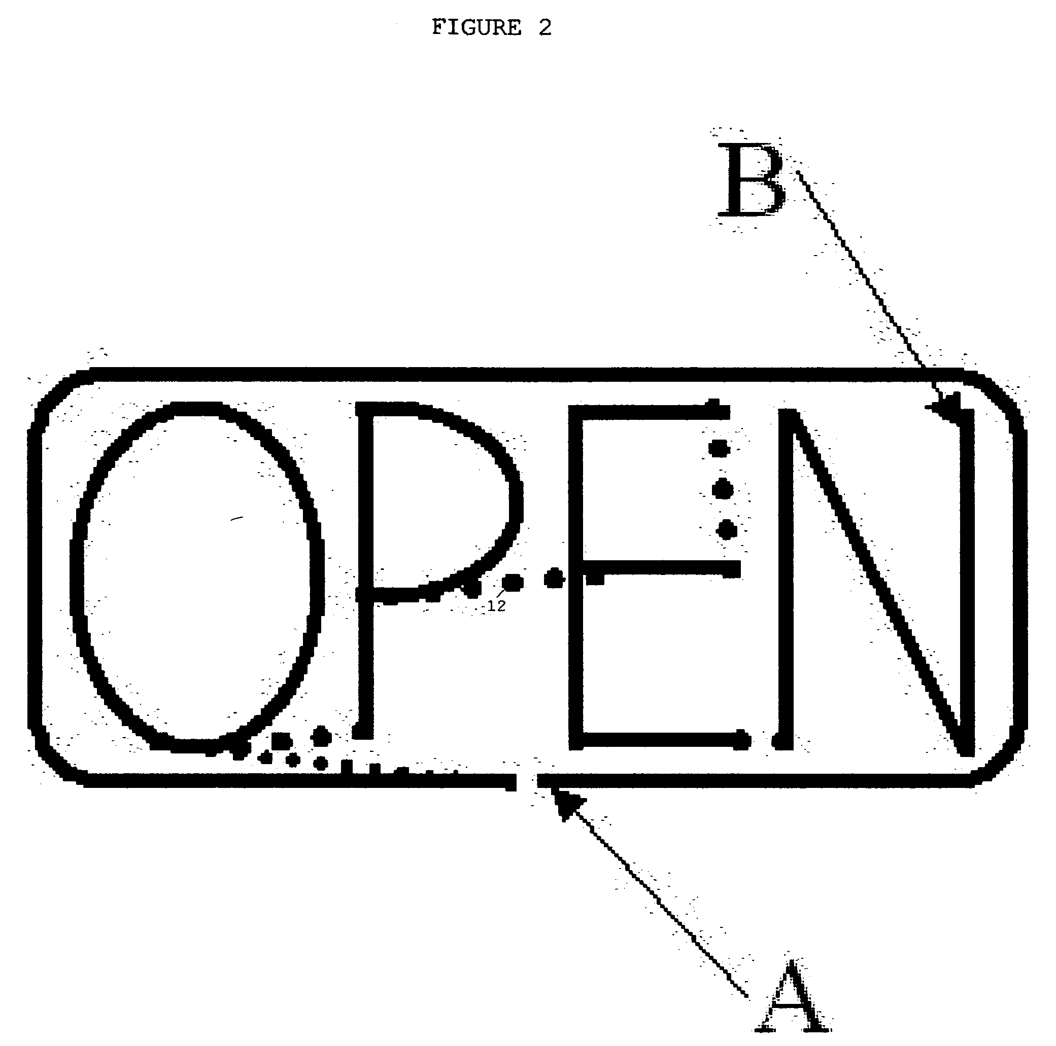
[0014] It was discovered that when gaps are required in the glowing wire to replicate neon signs or to create artistic effects, dark opaque paint or other suitable material can be used to coat the outer surface of the wire, therefore muting the glow in those areas.
[0015] It was further discovered, as a feature of the present invention, that coating the outer surfaces of the wire with a clear protective layer resulted in increased stiffness and durability of the sculpture without reducing the glow from the electrical stimulation of the wire. This allows the wire to be mounted to other structures to simulate real neon signs in small scales.
[0016] As another feature of the present invention, it was discovered that using heat shrinkable tubing over soldered connections in the sculpture could be used to simulate the effect of the actual glass-to-wire electrical cathodes in common use in full-scale neon signs. This feature also facilitates the fabrication of multicolor replicas whereas different colors of electroluminescent wire can be soldered together to form multicolored replicas.

Problems solved by technology

Because of the small diameter required at scales below 6″=1 Foot scale, real neon gas-filled tubes cannot operate effectively because small diameter glass tubes are extremely brittle and the electrical properties of voltage and current required to produce a glow in such a small neon-filled cavity is impractical.
In addition, there are no individual lights small enough to represent continuous lighting in small scales below 6″−1 foot scale.

Method used


Image

  • Method of creating miniature electrical glowing signs and sculptures
  • Method of creating miniature electrical glowing signs and sculptures
  • Method of creating miniature electrical glowing signs and sculptures

Examples


Embodiment Construction

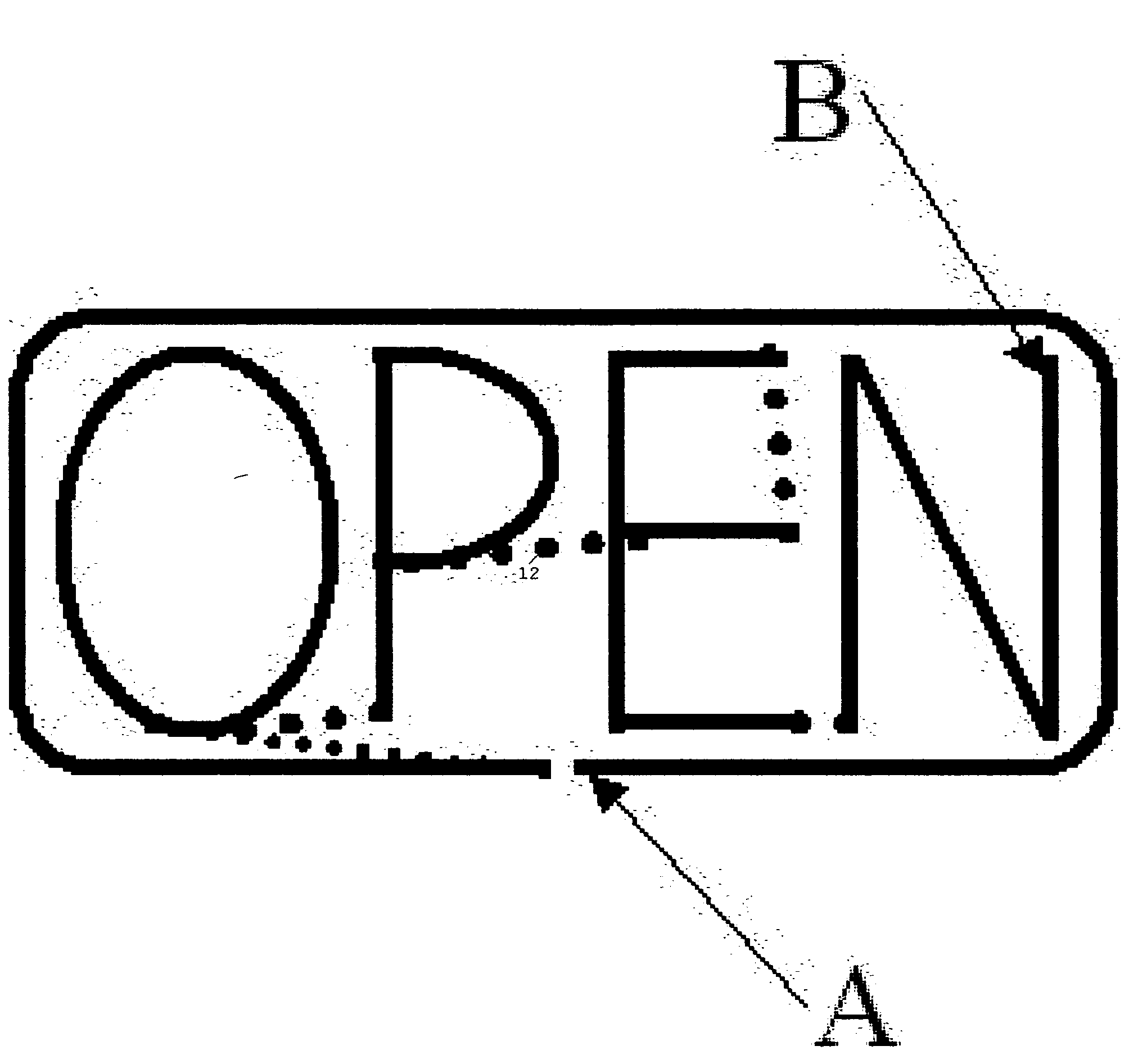
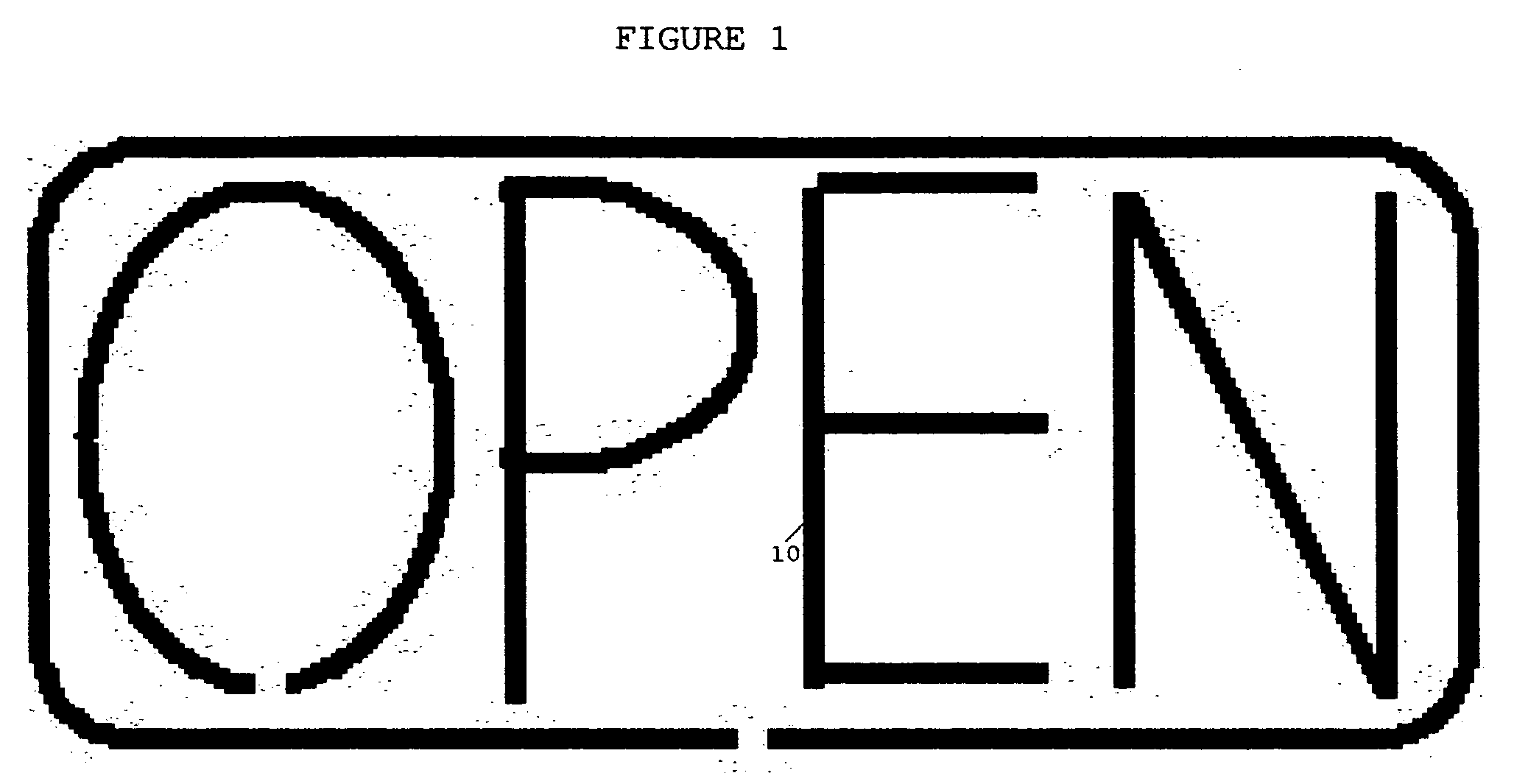
[0024] Referring to FIG. 1, the invention makes use of one or more pieces of small diameter electroluminescent (EL) wire also referred to as an electroluminescent cable or electroluminescent rope, bent into shapes to simulate glass neon-filled tubes at small scales as shown in the specific embodiment of an “OPEN” Neon sign representation 10. Referring to FIG. 2, dark paint or other forms of coating 12 are used at various locations to cover up the glow from the wire and create the impression of gaps in the sculpture or sign. Referring to FIG. 3, when different colors are needed to create connection 14, the electroluminescent wire is soldered together at the proper locations. Referring to FIG. 4, a Joining with opaque coating 16 between large diameter and smaller diameter electroluminescent wires can be covered with coating 12 to represent a connection 14 between a neon tube and an electrical wire such as is found in real neon signs at large scale. A suitable power source is used to c...


PUM


Abstract

A description of the method used to create miniature replicas of neon signs and sculptures. Electroluminescent (EL) wire is bent into shapes to replicate letters, numerals, arcs, polygons and other shapes as necessary to replicate actual articles at larger scales. Different colors of EL wire are used as necessary and soldered together at the ends to create multicolor signs and sculptures. A suitable alternating current power source is applied to the wire to cause it to glow or sparkle. When gaps are required in the glowing wire to replicate neon signs or to create artistic effects, dark opaque paint or other suitable material is used to coat the outer surface of the wire, therefore muting the glow in those areas.

Description

RELATED APPLICATIONS [0001] The present application is related to U.S. Pat. No. 4,950,509, issued Aug. 21, 1990, for MINIATURE TREE SCULPTURE, by DeMott; Donald T., included by reference herein. [0002] The present application is related to United States patent number 20040058615, issued Mar. 25, 2004, for ELECTROLUMINESCENT SIGN, by Murasko, Matthel; et al., included by reference herein. [0003] The present application is related to United States patent number 20040047142, issued Mar. 11, 2004, for LIGHTED ARCHITECTURAL MESH, by Goslee, Daniel Lee, included by reference herein. [0004] The present application is related to U.S. Pat. No. 5,229,149, issued Jul. 20, 1993, for STRAWBERRY SIMULATING A ROSE BUD, by Cone, Shari L., included by reference herein.FIELD OF THE INVENTION [0005] The present invention relates to miniature sculptures and methods of fabricating such sculptures and, more particularly, the present invention relates to making miniature sculptures using electrolunimescen...

Claims


Application Information

Patent Timeline
IPC IPC(8): G09F13/26
CPCG09F13/26
Inventor BEVILACQUA, ANDREW THOMASBEVILACQUA, JOANN CYNTHIA
Owner BEVILACQUA ANDREW THOMAS
Why Eureka
Try Eureka