
Impulse radio systems with multiple pulse types

a radio system and pulse type technology, applied in the field of radio communication systems, can solve the problems of small interference to narrow bandwidth receivers, low performance, and receivers that cannot fully resolve all multi-path components, and achieve the effect of reducing interferen

Inactive Publication Date: 2006-02-23
MITSUBISHI ELECTRIC RES LAB INC
View PDF13 Cites 13 Cited by
  • Summary
  • Abstract
  • Description
  • Claims
  • Application Information

AI Technical Summary

Benefits of technology

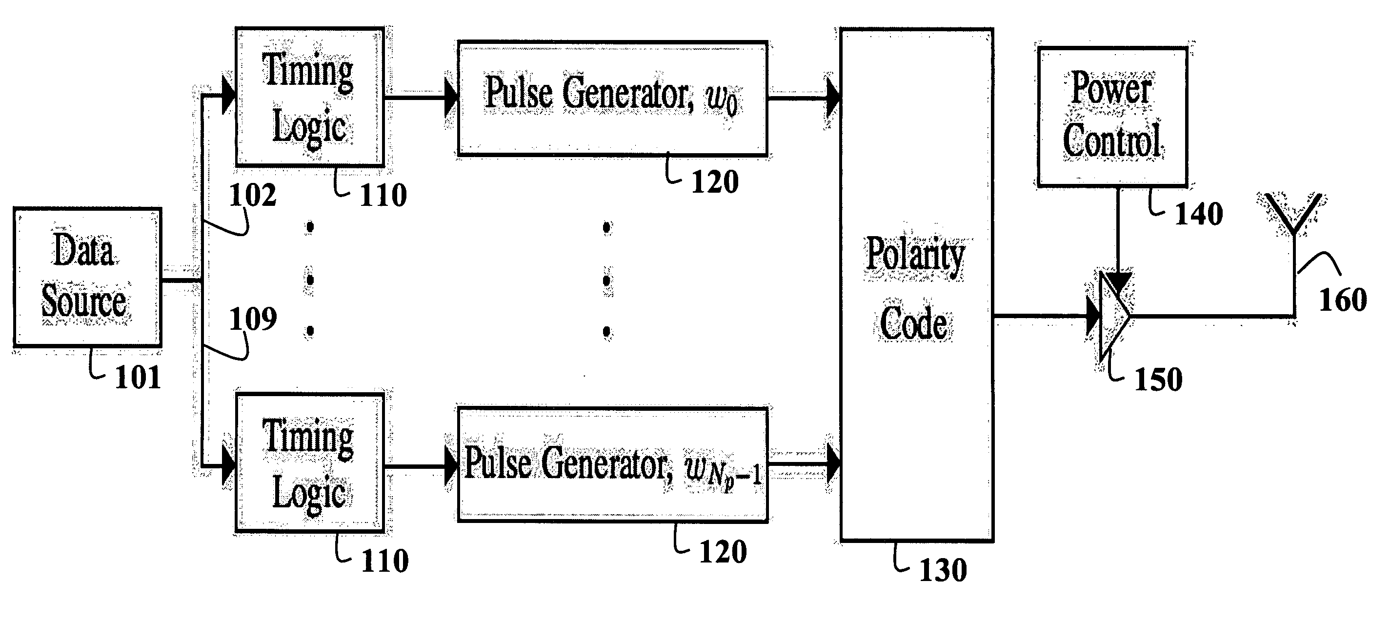
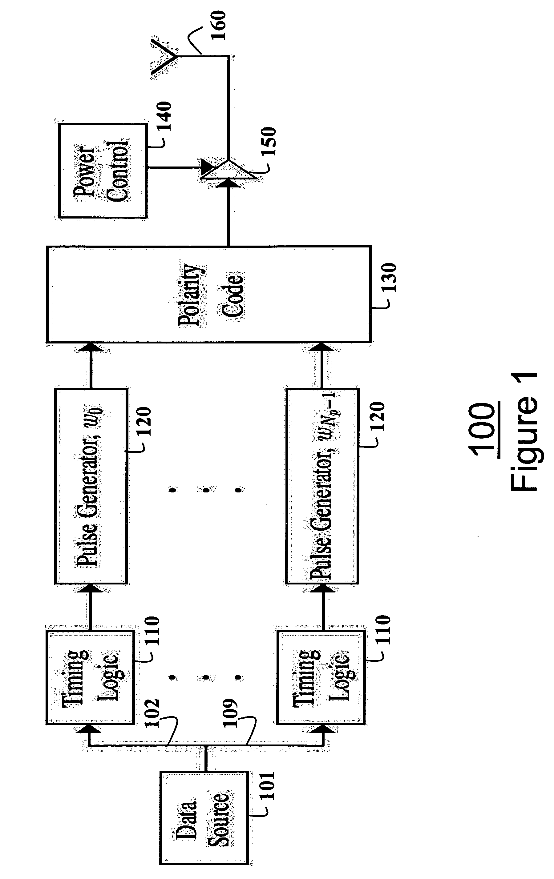
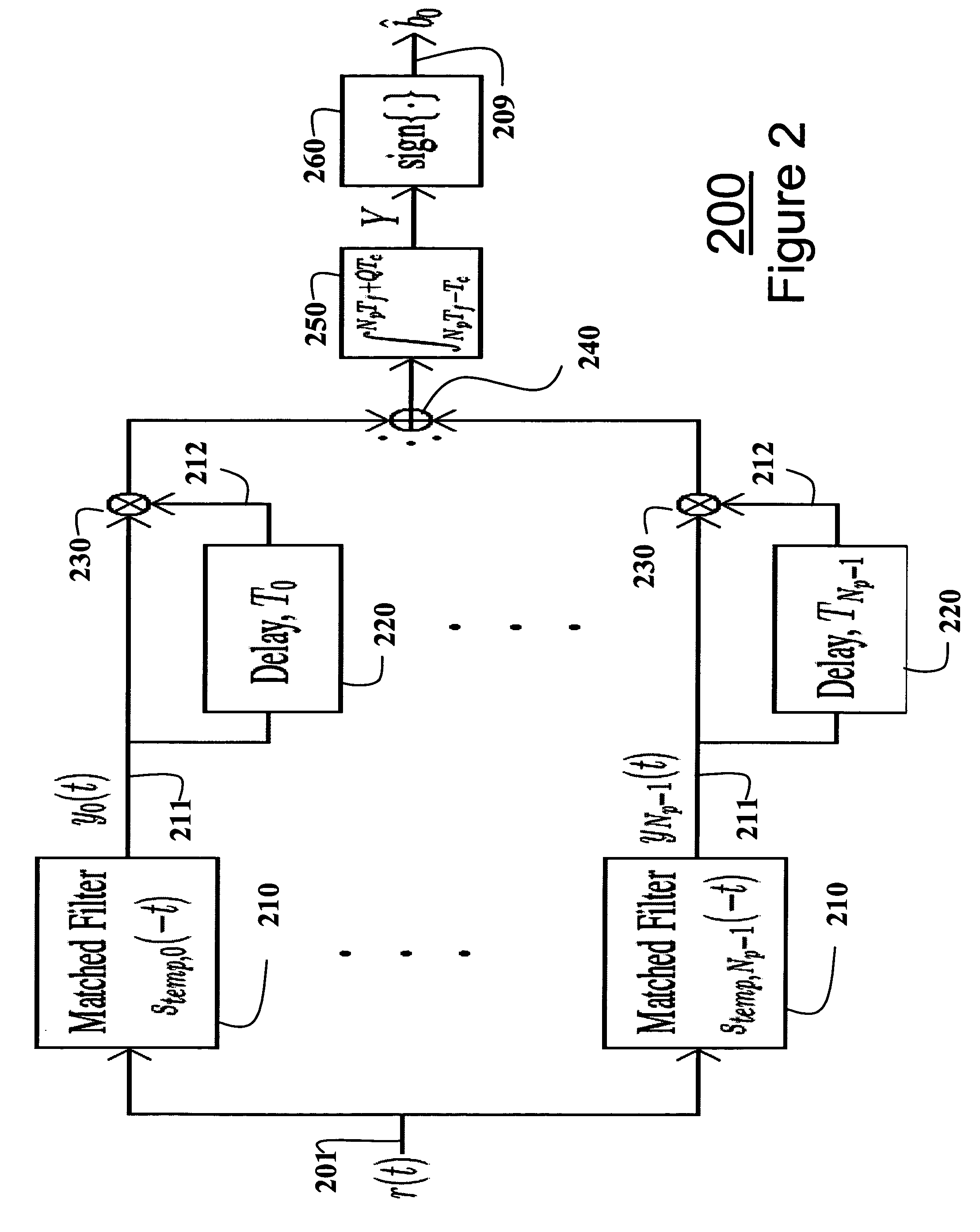
[0009] The invention provides a method and system for transmitting and receiving radio signals in a multi-pulse transmitted-reference impulse ultra wideband communications system. To transmit a data symbol, a transmitter sends multiple reference pulses, each being of a different type, and multiple data pulses corresponding in number and types to the number and types of the reference pulses. The pulses are sent according to a predetermined structure that depends on the number and types of the pulses. By using multiple different types of pulses, interference is reduced.
[0012] The system according to the invention facilitates the use of multiple different pulses for improved interference rejection. Complexity constraints, interference effects and the signal-to-noise ratio of the system are the main factors to be considered when selecting the number of different pulse types Np.

Problems solved by technology

Therefore, interference to narrow bandwidth receivers is also small.
That means that the receiver does not fully resolve all multi-path components, and the performance is less than ideal due to the inherent channel estimation and combining problem.
Increasing the number of rake fingers increases the complexity and cost of the system.
Unfortunately, the output of the multiplier has a very poor signal-to-noise ratio (SNR) due to non-linear operations on noise terms when forming the decision variable and due to the inherent energy loss when transmitting the reference pulse.
That results in large noise-times-noise terms that are integrated over the time.
However, overall, the transmitted reference scheme has a worse performance when compared with the ideal rake approach, due to the noise products.

Method used


Image

  • Impulse radio systems with multiple pulse types
  • Impulse radio systems with multiple pulse types
  • Impulse radio systems with multiple pulse types

Examples


Embodiment Construction

[0018] Signal Structure

[0019] A transmitted signal s(t) for an ultra wide bandwidth (UWB) system according to the invention is expressed as s⁡(t)=1Nf⁢∑i=-∞∞⁢∑n=0Np-1⁢sn,i⁡(t),(1)

where Nf is the number of pulses per information bit or data symbol, Np is the number of different pulse types, with n being an index for the pulse type, and i being an index for the data symbol. For simplicity of the expressions, the number of pulses Nf is assumed to be an even multiple of the number of data symbols. However, this is not required. The variable sn,i(t) is expressed as sn,i⁡(t)=⁢∑j=iNf⁢ / ⁢(2⁢Np)(i+1)⁢Nf2⁢Np-1⁢[djNp+n⁢wn⁡(t-(2⁢Np⁢j+n)⁢Tf-cjNp+n⁢Tc)+⁢b⌊2⁢Np⁢j⁢ / ⁢Nf⌋⁢djNp+n⁢wn(t-(2⁢Np⁢j+n)⁢Tf-⁢cjNp+n⁢Tc-Tn)].(2)

[0020] In equation (2), wn(t) is the UWB pulse of type n, Tf is the frame interval, and Tc is the chip interval. A time-hopping (TH) code is denoted by cj, which is an integer taking values in the set {0, 1, . . . , Nc−1}, with Nc being the number of chips per frame. This prevents catas...


PUM


Abstract

A method signals in an ultra-wide bandwidth network. A data symbol is generated. A set of reference pulses is transmitted for the data symbol. Each reference pulse is of a different type. One data pulse is also transmitted for each reference pulse. A type of each data pulse is identical to the type of the corresponding reference pulse.

Description

FIELD OF THE INVENTION [0001] The present invention relates generally to radio communication systems, and more particularly to ultra wide bandwidth (UWB) systems. BACKGROUND OF THE INVENTION [0002] With the release of the “First Report and Order”, Feb. 14, 2002, by the Federal Communications Commission (FCC), interest in ultra wide bandwidth (UWB) systems has increased considerably. UWB systems spread information over a wide bandwidth of at least 500 MHz. Due to this spreading operation, a power spectral density is small. Therefore, interference to narrow bandwidth receivers is also small. [0003] Transmitters for low data rate transmitted reference UWB systems (TR-UWB) are described by R. Hoctor and H. Tomlinson, “Delay-hopped transmitted-reference RF communications,”Proceedings of the IEEE Conference of Ultra Wideband Systems and Technologies 2002 (UWBST'02), pp. 265-269, May 2002, N. v. Stralen, A. Dentinger, K. Welles II, R. Gaus, R. Hoctor, and H. Tomlinson, “Delay hopped transm...

Claims


Application Information

Patent Timeline
IPC IPC(8): H04B1/69
CPCH04B1/71632H04B1/719H04B1/71635
Inventor SAHINOGLU, ZAFERGEZICI, SINAN
Owner MITSUBISHI ELECTRIC RES LAB INC
Learn More