
High spatial resolution imaging

a high spatial resolution and imaging technology, applied in the field of high spatial resolution measuring a sample, can solve the problem of high cost of application of the known method, and achieve the effect of high spatial resolution

Active Publication Date: 2006-02-23
MAX PLANCK GESELLSCHAFT ZUR FOERDERUNG DER WISSENSCHAFTEN EV
View PDF5 Cites 90 Cited by
  • Summary
  • Abstract
  • Description
  • Claims
  • Application Information

AI Technical Summary

Benefits of technology

The present patent describes a way to measure samples very precisely using light. This involves selectively transferring a substance between two states that have different optical properties using a special device called an optical switch. By doing this, researchers can create precise measurements on specific parts of a sample while ignoring other areas. Overall, this technique allows for highly accurate data collection without compromising the integrity of the sample.

Problems solved by technology

The technical problem addressed in this patent text is the need for a method of high spatial resolution imaging a structure of a sample that can be carried out with comparatively low cost and effort with regard to the required apparatuses. Existing methods such as multi-photon absorption and generation of higher harmonics have limitations in terms of the required laser power and saturation thresholds. Other methods such as STED and GSD have short life times and require high intensity stimulation. There is also a need for a method that can use fluorescence markers that are naturally occurring or can be deliberately switched between fluorescent and non-fluorescent states.

Method used


Image

  • High spatial resolution imaging
  • High spatial resolution imaging

Examples


Embodiment Construction

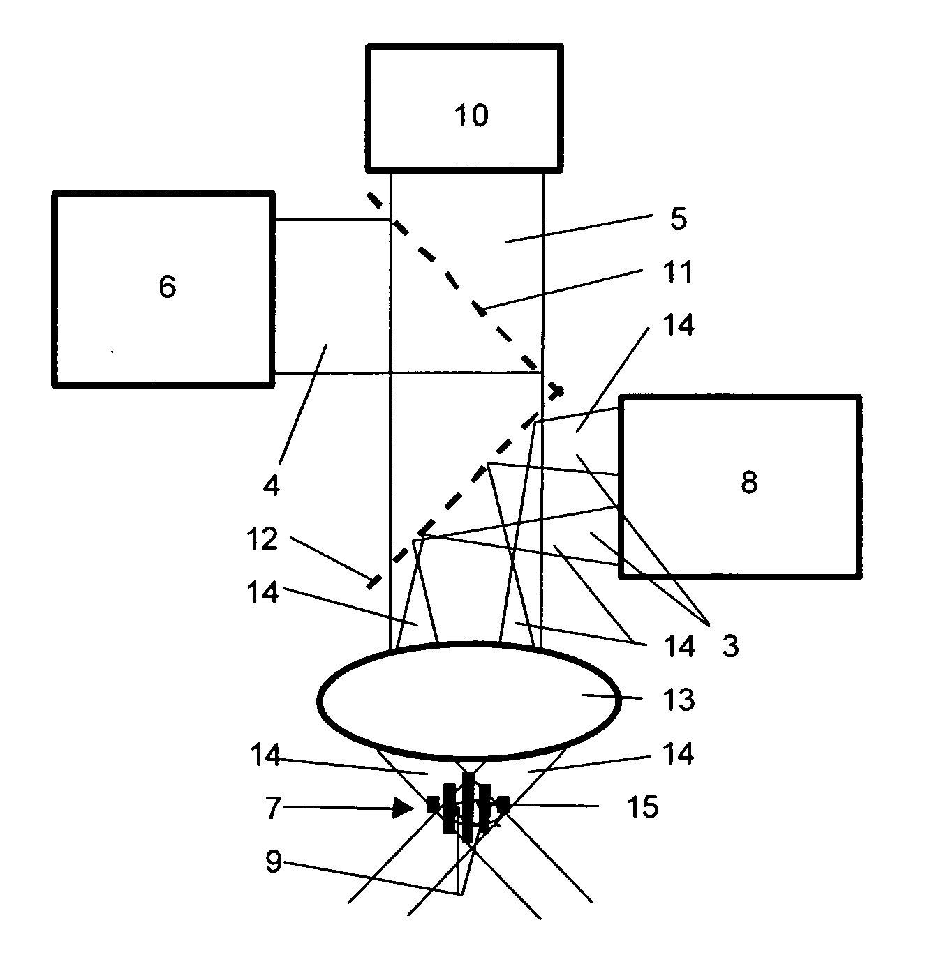
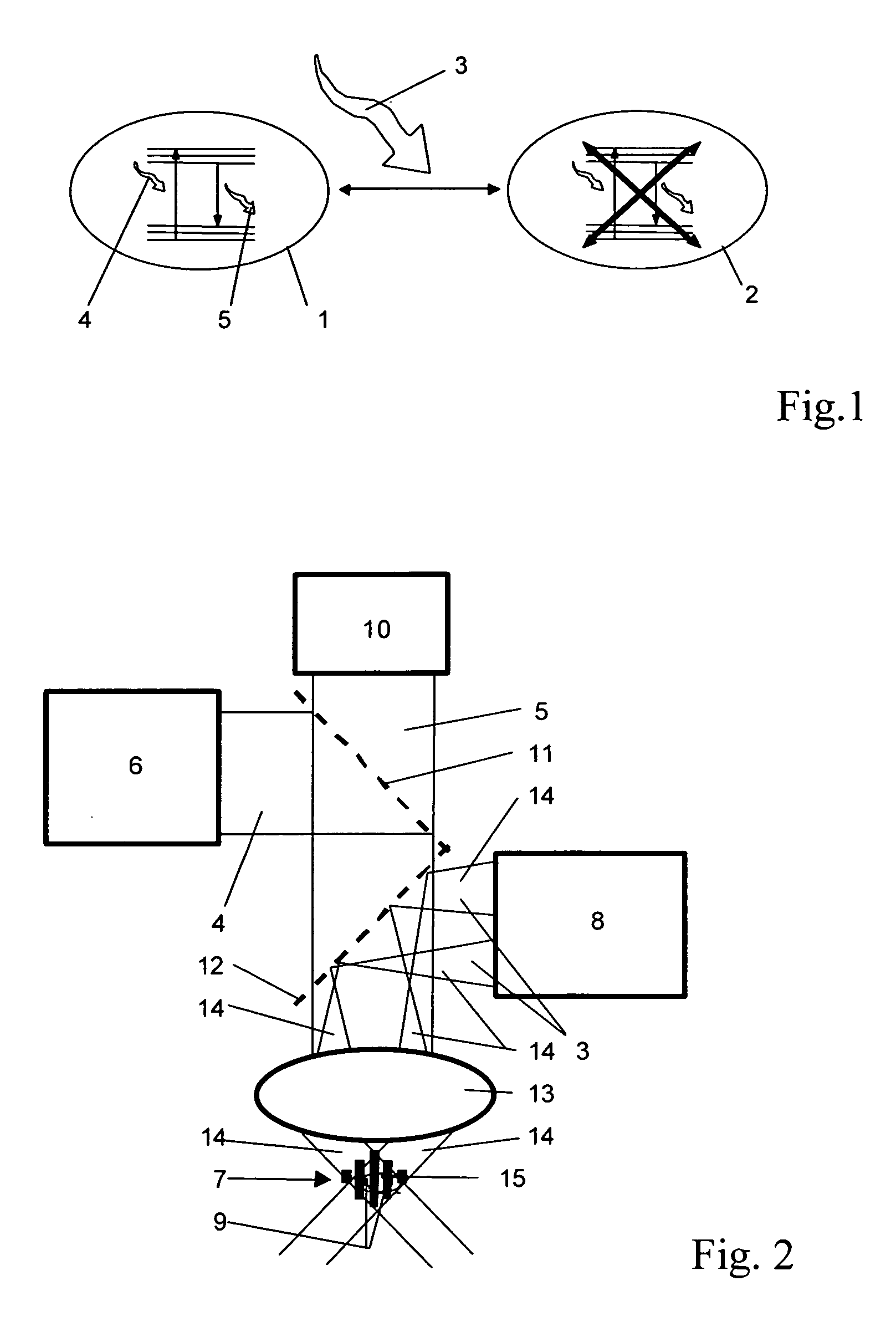
[0020] Using substances having two states with different optical properties is a central aspect of the invention. Further, it is important that the substance may be purposefully switched with a switch over signal out of the first into the second state. This process is reversible. I.e. the substance can also be returned to the first state. The optical properties of the substance in the first state differ from those in the second state in that only the optical properties of the first state support the measurement signal. However, it is not necessary that the relevant optical properties are “binary”, i.e. it is not necessary that they are present in the one state at 100% and in the other state at 0%. Instead, it is sufficient, if the relevant optical properties are different to such an extent that the measurement signal my at least mainly be regarded as associated with the first state.

[0021] In contrast to the state of the art in the field of fluorescence microscopy the invention make...


PUM


Abstract

In a method of high spatial resolution imaging a structure of a sample, the structure is marked with a substance. The substance is selected from a group of substances which are capable of being repeatedly transferred out of a first state having first optical properties into a second state having second optical properties by means of an optical switch over signal, and which are capable of returning out of the second state into the first state, the two states differing with regard to at least one criteria. Within areas of the sample the sample is transferred into the second state by means of the optical switch over signal with which at least one spatially limited area of the sample is purposefully omitted. An optical measurement signal is detected, which is associated with the substance in the first state and which comes out of a detection area including both the area purposefully omitted with the switch over signal and areas in which the substance has been transferred into to second state.

Description


Claims


Application Information

Patent Timeline
Owner MAX PLANCK GESELLSCHAFT ZUR FOERDERUNG DER WISSENSCHAFTEN EV
Learn More