
System, method and storage medium for providing a bus speed multiplier

a technology of memory subsystem and bus speed multiplier, which is applied in the field of memory subsystem with bus speed multiplier, can solve the problems of increasing the probability, increasing the number of modules that may be attached to the stub bus, and affecting multiple memory modules along the bus

Inactive Publication Date: 2006-02-16
IBM CORP
View PDF99 Cites 79 Cited by
  • Summary
  • Abstract
  • Description
  • Claims
  • Application Information

AI Technical Summary

Benefits of technology

The present invention is a memory subsystem with a bus speed multiplier. This means that the memory subsystem has a faster data rate than the memory modules it uses. The memory subsystem includes a memory controller and memory busses that operate at four times the speed of the memory modules. The memory controller and memory modules are connected by a packetized multi-transfer communications interface using the memory busses. The technical effect of this invention is faster data transfer and improved performance of the memory subsystem.

Problems solved by technology

The technical problem addressed in this patent is how to improve the efficiency and flexibility of memory subsystems while reducing the likelihood of failures affecting multiple memory modules.

Method used


Image

  • System, method and storage medium for providing a bus speed multiplier
  • System, method and storage medium for providing a bus speed multiplier
  • System, method and storage medium for providing a bus speed multiplier

Examples


Embodiment Construction

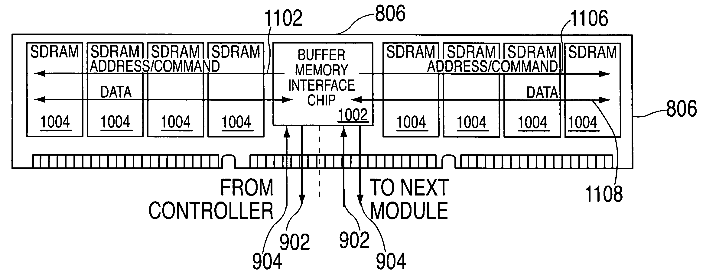
[0028] Exemplary embodiments of the present invention provide a high speed and high reliability memory subsystem architecture and interconnect structure that includes a single-ended point-to-point interconnection between any two subsystem components. The memory subsystem further includes a memory control function, one or more memory modules, one or more high speed busses operating at a four-to-one speed ratio relative to the DRAM data rate and a bus-to-bus converter chip on each of one or more cascaded modules to convert the high speed bus(ses) into the conventional double data rate (DDR) memory interface. The memory modules operate as slave devices to the memory controller, responding to commands in a deterministic or non-deterministic manner, but do not self-initiate unplanned bus activity other than the reporting of operational errors. Memory modules can be added to the cascaded bus, with each module assigned an address to permit unique selection of each module on the cascaded bu...


PUM


Abstract

A memory subsystem for providing a bus speed multiplier. The memory subsystem includes one or more memory modules operating at a memory module data rate. The memory subsystem also includes a memory controller and one or more memory busses. The memory busses operate at four times the memory module data rate. The memory controller and the memory modules are interconnected by a packetized multi-transfer interface via the memory busses.

Description


Claims


Application Information

Patent Timeline
Owner IBM CORP
Learn More