
Method and apparatus for closed loop transmission

a closed-loop transmission and transmission method technology, applied in the field of communication systems, can solve problems such as degrading the performance of closed-loop transmission in systems, and achieve the effects of increasing the transmit power per subcarrier, high flexibility, and signaling efficiency

Active Publication Date: 2006-02-16
GOOGLE TECH HLDG LLC
View PDF12 Cites 230 Cited by
  • Summary
  • Abstract
  • Description
  • Claims
  • Application Information

AI Technical Summary

Benefits of technology

[0027] One aspect of the invention is optional signaling for determining the presence and characteristics of the Sounding Zone. The BS can signal the presence of the sounding zone by transmitting an information element (IE) in the uplink control channel (e.g., the UL-MAP in the IEEE 802.16 standard). This IE can indicate the start time (generally the number of bauds into the UL) and duration (generally measured in number of OFDM bauds). If the sounding baud is not intended to occupy the entire uplink bandwidth, then the IE will contain information specifying the frequency occupancy of the sounding zone. Note that signaling to specify the Sounding Zone is not required—rather, it is helpful for reducing the overhead in the actual sounding assignments made to specific SSs.
[0032] Additional aspects of the invention are described in later sections of the specification. The present invention has a number of benefits: The signaling method provides a high level of flexibility and signaling efficiency. The method enables the dynamic allocation of an UL sounding resource to multiple SSs and handles the case where the SSs have single or multiple transmit antennas. The method also provides multiple techniques for making the sounding waveforms separable by the BS, which enables multiple SS antennas (whether the antennas are all on one device or are located on multiple SSs) to sound the UL on the same time-frequency sounding resource. The signaling method is also complementary with other methods of determining the UL channel response. For example, the sounding operations can be disabled (or turned off) if the BS can determine the UL channel response from the data transmitted by the SS on the UL. As part of the method for providing multiple separable sounding waveforms, the signaling method provides the means to decimate the sounding transmissions in frequency so as to increase the transmit power per subcarrier to better support SSs operating in low SNR environments. Also, the waveforms used for sounding transmission are designed to have low peak-to-average power ratio and to have the ability to suppress other cell interference by virtue of their cross-correlation characteristics. Finally, the sounding waveforms provided by the proposed signaling method are designed to enable effective channel estimation at the BS so that the time variations in the channel response can be tracked.

Problems solved by technology

However, in modern digital communication systems, traffic (such as web browsing) is often asymmetric, meaning that there may not be an uplink transmission associated with each downlink transmission.
These issues can severely degrade the performance of closed loop transmission in systems based on reciprocity.

Method used


Image

  • Method and apparatus for closed loop transmission
  • Method and apparatus for closed loop transmission
  • Method and apparatus for closed loop transmission

Examples


Embodiment Construction

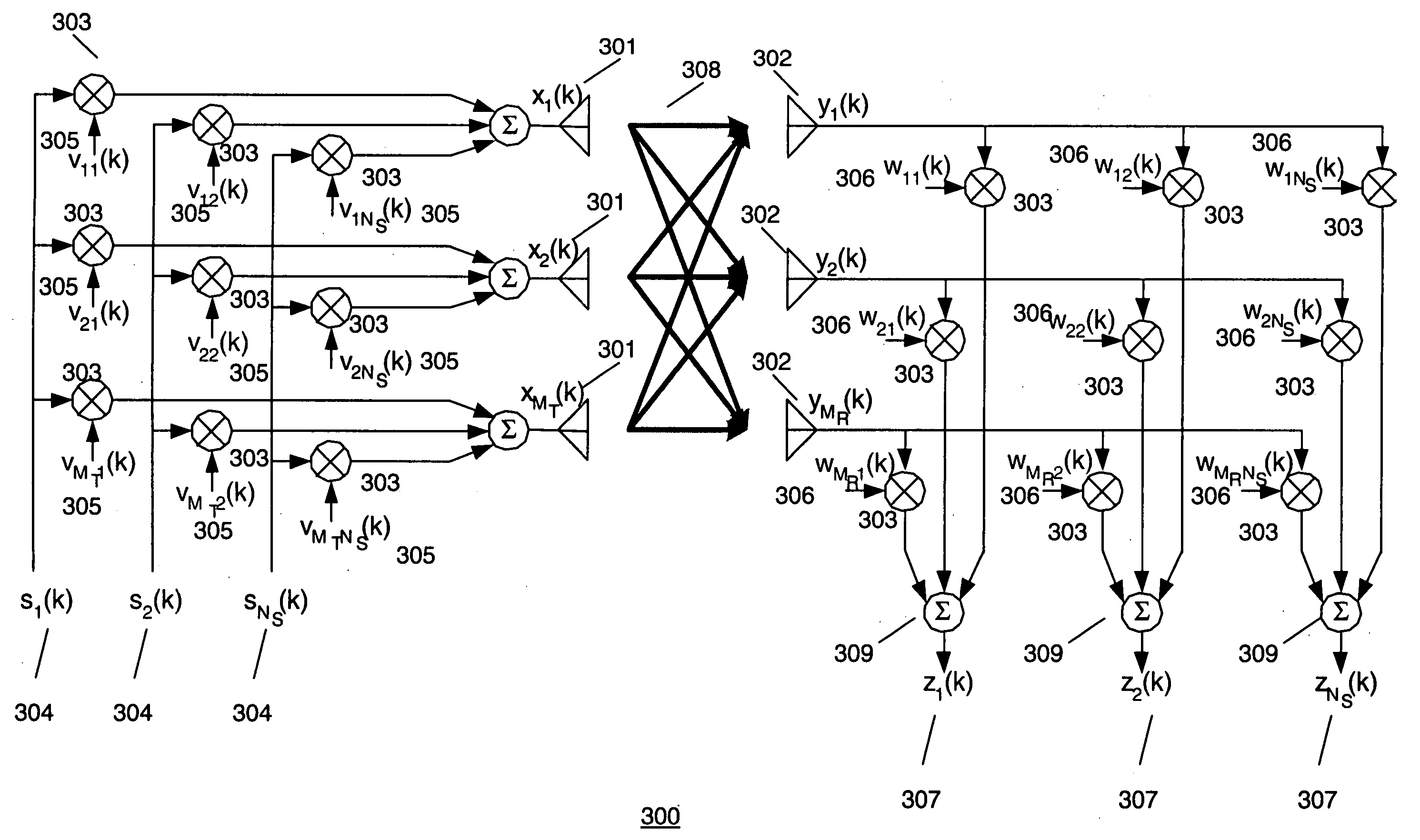
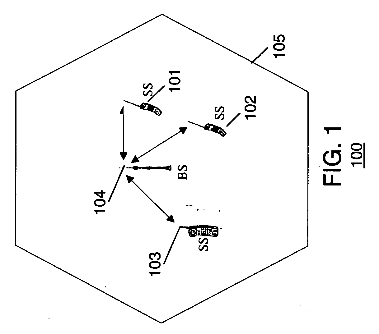
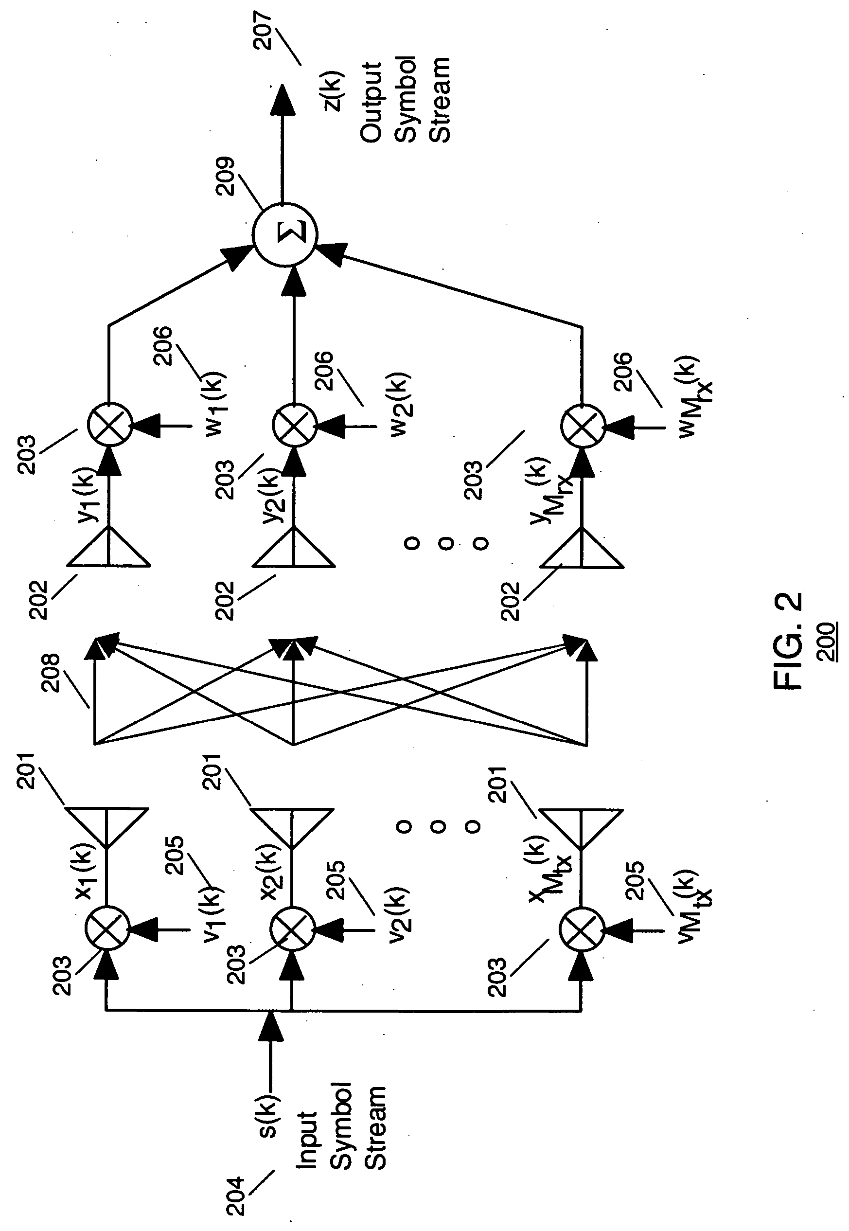
[0033] Turning now to the drawings, wherein like numerals designate like components, FIG. 1 is a block diagram of communication system 100. Communication system 100 comprises a plurality of cells 105 (only one shown) each having a base station (BS, or base station) 104 in communication with a plurality of subscriber stations (SSs) 101-103. If closed loop transmission is to be performed on the downlink to SS 101, the BS 104 can be referred to as a source communication unit, and the SS 101 can be referred to as a target communication unit. If closed loop transmission is to be performed on the uplink from SS 101 to the BS 104, SS 101 can be referred to as a source communication unit, and the BS 104 can be referred to as a target communication unit. In the preferred embodiment of the present invention, communication system 100 utilizes an Orthogonal Frequency Division Multiplexed (OFDM) or multicarrier based architecture including Adaptive Modulation and Coding (AMC). The architecture m...


PUM


Abstract

In a wireless communication system, a method and apparatus for closed loop transmission is disclosed. In accordance with the preferred embodiment of the present invention, a time frequency portion of an uplink frame is dynamically reserved as a sounding zone for uplink channel sounding. A first message is transmitted to a first subscriber station in a downlink frame assigning a time-frequency resource within the sounding zone, and a sounding waveform. Furthermore, a signal is received from the subscriber station within the assigned time-frequency resource, a partial channel response is determined from the received sounding signal, and the subsequent transmission to the subscriber station is tailored based on the at least partial channel response.

Description

FIELD OF THE INVENTION [0001] The present invention relates generally to communication systems, and in particular, to a method and apparatus for closed loop transmission. BACKGROUND OF THE INVENTION [0002] In mobile broadband cellular communication systems, there are several physical layer techniques that require the transmitter to be provided with knowledge of the channel response between the transmitter and receiver. Transmission techniques that make use of the channel response between the transmitter and receiver are called closed-loop transmission techniques. One example of closed-loop transmission is the use of a closed-loop transmit antenna array at the transmitter. A closed loop transmit antenna array is an array of multiple transmit antennas where the signals fed to each antenna are weighted in such a way as to control the characteristics of the transmitted signal energy according to some pre-defined optimization strategy. Generally, the closed-loop transmit antenna array we...

Claims


Application Information

Patent Timeline
IPC IPC(8): H04Q7/20H04J99/00H04W72/04
CPCH04L5/0094H04L25/0226H04L25/03343H04L2025/03414H04L2025/03426H04L27/2613H04L2025/03815H04W72/04H04L5/0023H04L5/0026H04L5/0051H04L2025/03796H04L5/0007H04L5/0048H04W28/26
Inventor VOOK, FREDERICK W.ZHUANG, XIANGYANGBAUM, KEVIN L.THOMAS, TIMOTHY A.
Owner GOOGLE TECH HLDG LLC
Learn More