
Embedded fluid mixing device using a homopolar motor

a technology of homopolar motor and mixing device, which is applied in the direction of positive displacement liquid engine, piston pump, other chemical processes, etc., can solve the problems of increasing the total amount of heat generated by such electronic devices, circuit geometries and device packaging continue to shrink, and modern circuit designers face many design challenges concerning thermal managemen

Active Publication Date: 2006-02-16
HARRIS CORP
View PDF23 Cites 3 Cited by
  • Summary
  • Abstract
  • Description
  • Claims
  • Application Information

AI Technical Summary

Benefits of technology

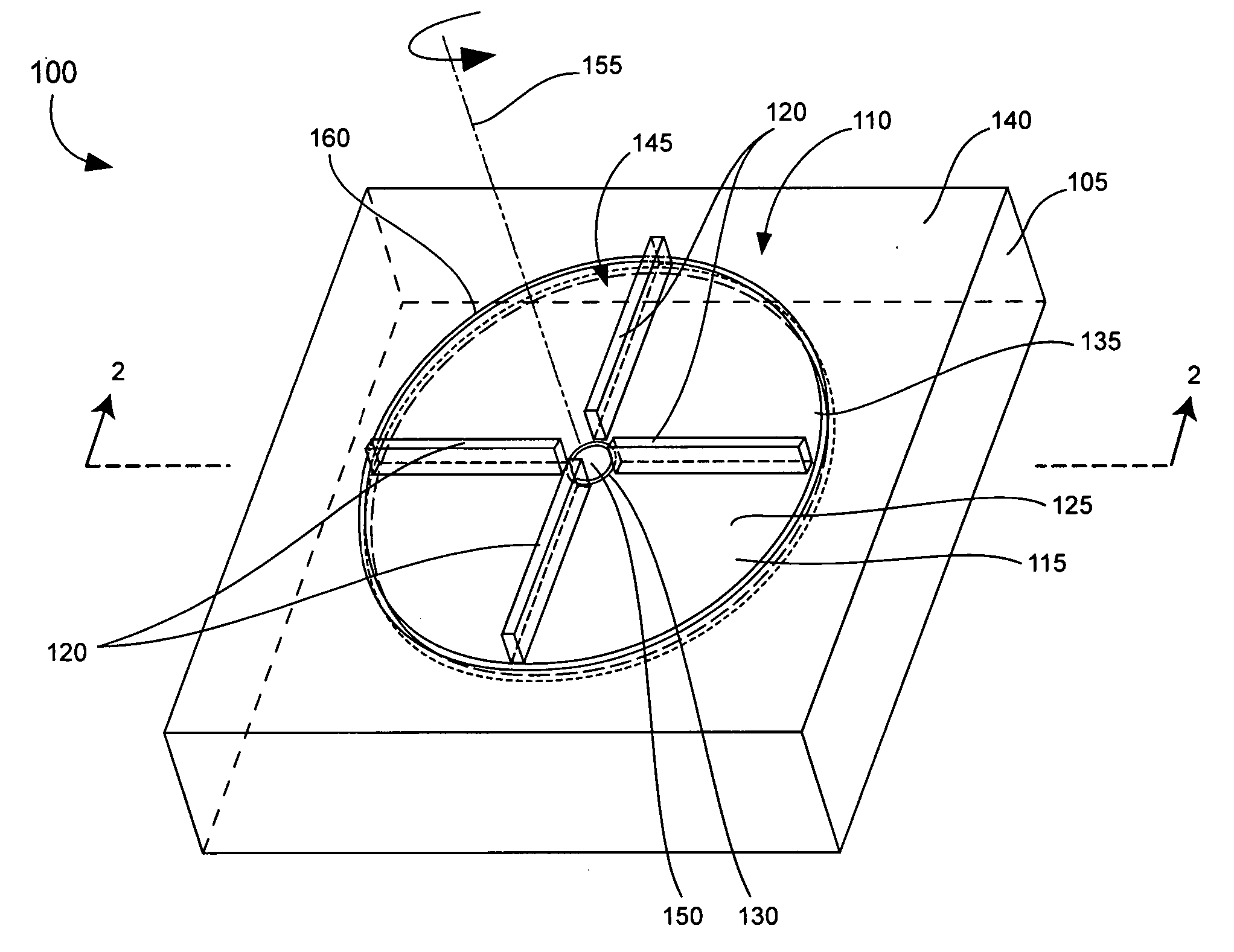
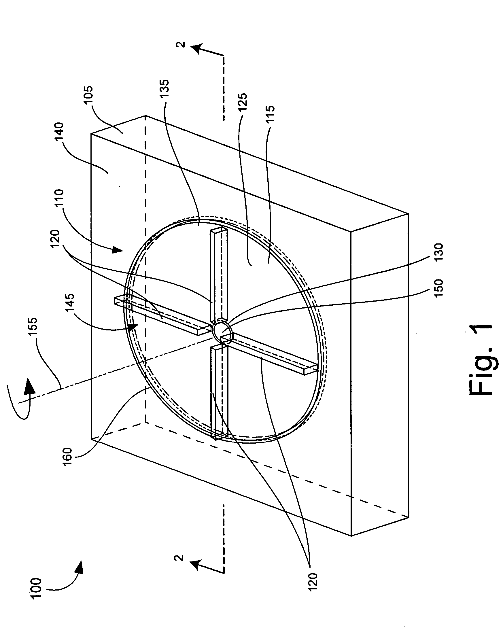
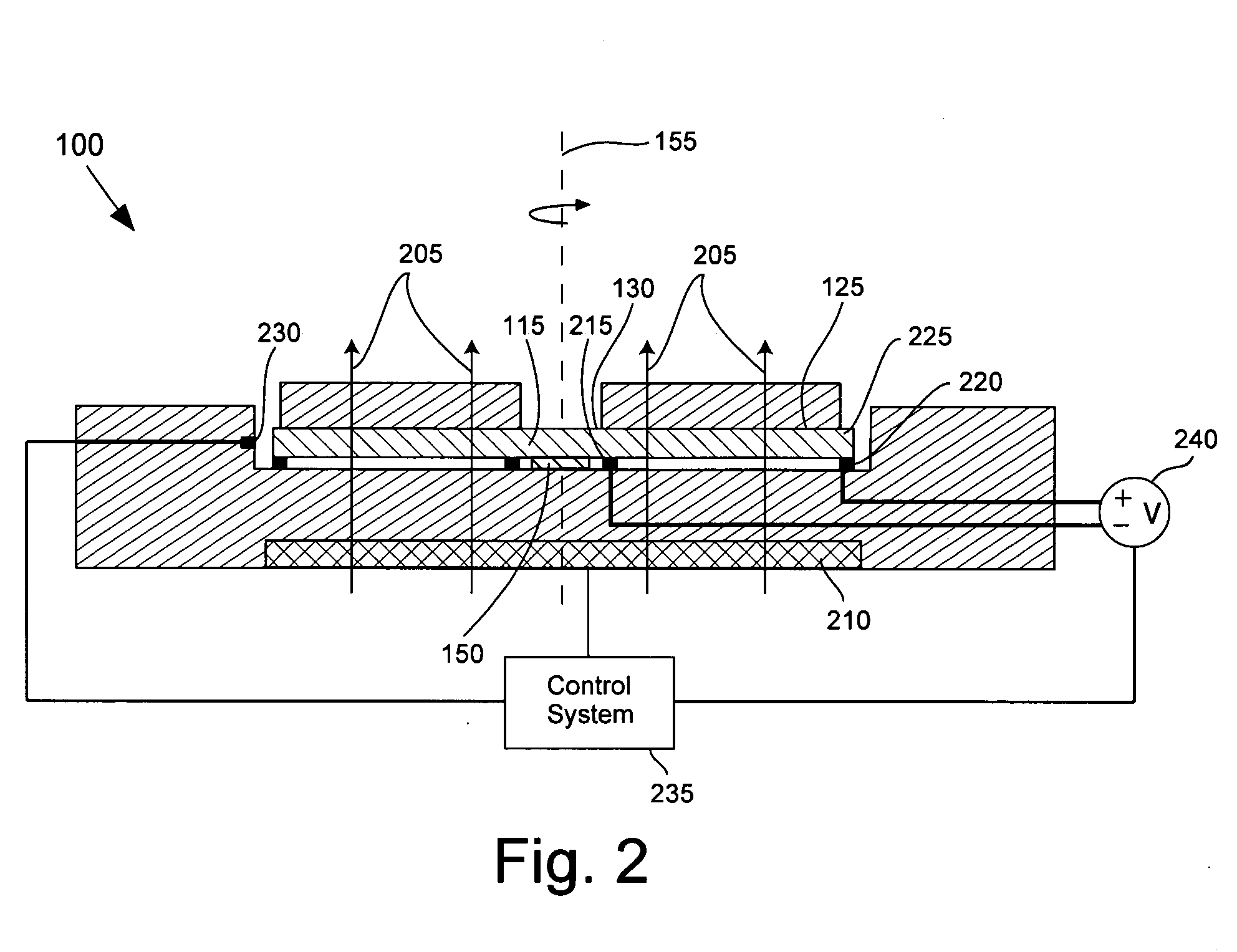
[0006] The present invention relates to a fluid displacement device having a homopolar motor. The homopolar motor includes a rotatable disk with at least one fluid displacement structure disposed thereon, for example a blade. The rotatable disk can be at least partially disposed within a cavity defined in a substrate, such as a ceramic substrate, a liquid crystal polymer substrate, or a semiconductor substrate. A closed loop control circuit can be included to control the rotational speed of the rotatable disk. For example, the control circuit can control a voltage source or a current source that applies voltage across the rotatable disk. The control circuit also can control a strength of a magnet that appl

Problems solved by technology

Microcells generate heat, though, thus adding to the total amount of heat that will be generated by such electronic devices.
Meanwhile, circuit geometries and device packaging continue to shrink.
Hence, modern circuit designers face many design challenges concerning thermal management.
However, such fans tend to be rather bulky, occupying valuable space within the devices.
Moreover, the fans often prove to be less than reliable, sometimes failing prior to any other device components.
In some instances, the loss of heat dissipation resulting from the failure of a fan actually causes other device components to overheat and fail.

Method used


Image

  • Embedded fluid mixing device using a homopolar motor
  • Embedded fluid mixing device using a homopolar motor
  • Embedded fluid mixing device using a homopolar motor

Examples


Embodiment Construction

[0013] The present invention relates to a fluid displacement device (fluid mixer) embedded within a substrate. Accordingly, the fluid mixer can be manufactured as a micro electromechanical system (MEMS) device. The fluid mixer can be embedded proximate to thermal generating devices and used to enhance the flow of convection currents around the devices, thereby providing a low profile solution for improving device heat dissipation. Accordingly, the use of bulky cooling fans which otherwise might be needed can be avoided. In another arrangement, the fluid mixer can be embedded within a substrate of a microfluidic system to mix fluids. Thus, the use of external mixing devices can be avoided.

[0014] The fluid mixer can be a stand alone device or can be advantageously integrated within a larger system. Examples of such larger systems can include electronic devices, fuel cells, fluidic systems, or any other device having a substrate. Importantly, the invention is not limited to any partic...


PUM


Abstract

A fluid displacement device (100) having a homopolar motor (110). The homopolar motor includes a rotatable disk (115) with at least one fluid displacement structure (120) disposed thereon. The fluid displacement structure can be a blade. The rotatable disk can be disposed within a cavity (145) defined in a substrate (105), such as a ceramic substrate, a liquid crystal polymer substrate, or a semiconductor substrate. A closed loop control circuit (235) can be included to control the rotational speed of the rotatable disk. For example, the control circuit can control a voltage source or a current source that applies voltage across the rotatable disk. The control circuit also can control a strength of a magnet (210) that applies a magnetic field (205) substantially aligned with an axis or rotation (155) of the rotatable disk.

Description

BACKGROUND OF THE INVENTION [0001] 1. Statement of the Technical Field [0002] The inventive arrangements relate generally to the field of micro electromechanical system (MEMS) devices. [0003] 2. Description of the Related Art [0004] As technology progresses, clock speeds of modern electronic devices continue to increase, resulting in a greater amount of heat being produced by device components. Additionally, efforts are currently under way to adapt very small fuel cells, called microcells, into portable electronic devices. For example, it is anticipated that microcells soon will be used for powering laptop computers and cell phones. Microcells generate heat, though, thus adding to the total amount of heat that will be generated by such electronic devices. Meanwhile, circuit geometries and device packaging continue to shrink. Hence, modern circuit designers face many design challenges concerning thermal management. [0005] Fans are a frequently used solution to dissipate heat within e...

Claims


Application Information

Patent Timeline
IPC IPC(8): B01F13/08
CPCB01F13/0059H02K31/02B01F13/0818H02K7/14Y10S366/601B01F33/30B01F33/452
Inventor KOENEMAN, PAUL B.
Owner HARRIS CORP
Learn More