
Spindle bracket for rear suspension

a technology for rear suspensions and pindle brackets, which is applied in resilient suspensions, interconnection systems, vehicle components, etc., can solve problems such as weak lateral direction, and achieve the effects of increasing lateral strength, reducing span, and increasing the number of welded parts

Inactive Publication Date: 2006-02-16
HYUNDAI MOBIS CO LTD
View PDF28 Cites 16 Cited by
  • Summary
  • Abstract
  • Description
  • Claims
  • Application Information

AI Technical Summary

Benefits of technology

[0009] Accordingly, the present invention has been made keeping in mind the above problems occurring in the prior art, and an object of the present invention is to provide a spindle bracket for rear suspensions, which has at a mounting hole thereof a lateral strength reinforcing piece to be secured between a trailing arm and a bracket body, thus increasing lateral strength.
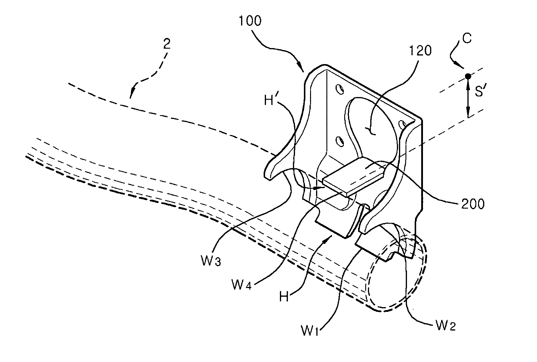
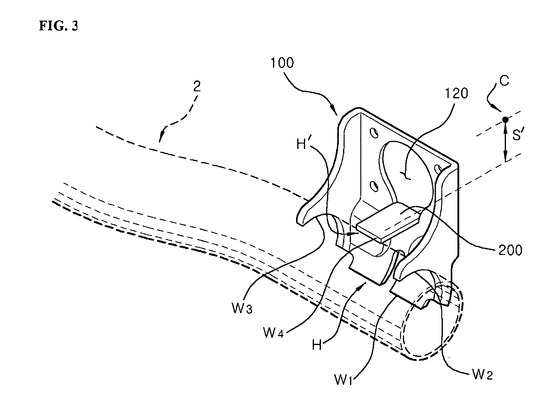
[0013] Such a construction increases the number of welded parts, and reduces the span between the welded part and a wheel center, thus increasing lateral strength.
[0014] Further, a reinforcing part for increasing lateral strength, namely, the lateral strength reinforcing piece, is fabricated using a part that is normally discarded during the manufacture of a mounting hole, so that an additional reinforcing part is not required but the previously discarded part is used to increase the lateral strength of the spindle bracket, thus maintaining low manufacturing costs thereof.

Problems solved by technology

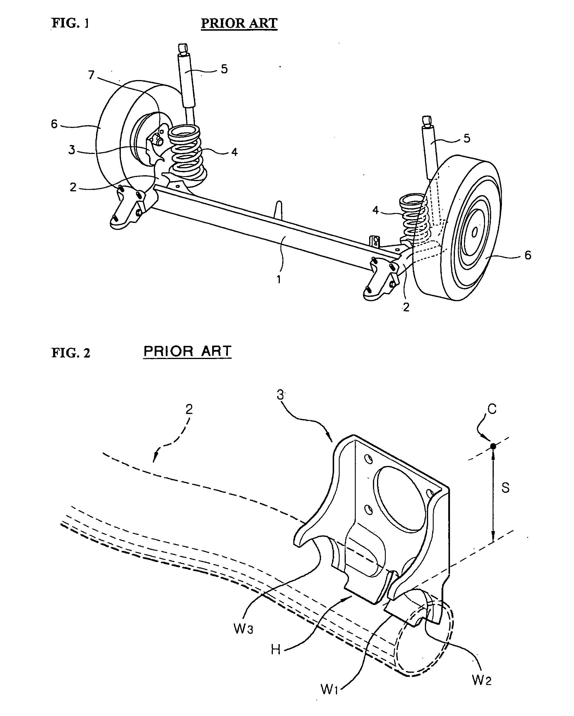
However, the conventional spindle bracket has a problem in that a span S between a wheel center C and the welded part W is large, so that it is weak in a lateral direction.

Method used


Image

  • Spindle bracket for rear suspension
  • Spindle bracket for rear suspension
  • Spindle bracket for rear suspension

Examples


Embodiment Construction

[0019] Reference now should be made to the drawings, in which the same reference numerals are used throughout the different drawings to designate the same or similar components.

[0020]FIG. 3 is a perspective view to show a spindle bracket for rear suspensions, according to a preferred embodiment of the present invention.

[0021] As shown in FIG. 3, the spindle bracket of this embodiment includes a bracket body 100 that is welded to a trailing arm 2 and has a mounting hole 120 into which a spindle (not shown) is inserted. The spindle bracket also includes a lateral strength reinforcing piece 200 which is secured between the trailing arm 2 and the bracket body 100.

[0022] The lateral strength reinforcing piece 200 is fabricated using a part that is left over from bridge work for increasing lateral strength during the manufacture of the mounting hole 120. The lateral strength reinforcing piece 200 comprises a rectangular plate which horizontally extends from a lower portion of an inner ...


PUM


Abstract

A spindle bracket for rear suspensions includes a bracket body welded to a trailing arm and having a mounting hole into which a spindle is inserted, and a lateral strength reinforcing piece secured between the trailing arm and the bracket body.

Description

RELATED APPLICATIONS [0001] The present disclosure relates to subject matter contained in priority Korean Application No. 10-2004-0062729, filed on Aug. 10, 2004, which is herein expressly incorporated by reference in its entirety. BACKGROUND OF THE INVENTION [0002] 1. Field of the Invention [0003] The present invention relates generally to a spindle bracket for rear suspensions and, more particularly, to a spindle bracket for rear suspensions, which has at a mounting hole thereof a lateral strength reinforcing piece to be secured between a trailing arm and a bracket body, thus increasing the ability to withstand lateral force, when the lateral force acts on outside wheels. [0004] 2. Description of the Related Art [0005] Generally, a suspension insulates a vehicle body from vibration or shocks transmitted through a road surface while a vehicle is running, thus preventing the vehicle body or baggage from being damaged and providing a smoother ride. As shown in FIG. 1, a rear suspensi...

Claims


Application Information

Patent Timeline
Patent Type & Authority Applications(United States)
IPC IPC(8): B60G21/05
CPCB60G7/008B60G21/051B60G2200/21B60G2206/50B60G2206/012B60G2206/20B60G2204/148B60G7/00B60G21/04
Inventor SHIN, KYOUNG-HOON
Owner HYUNDAI MOBIS CO LTD
Learn More